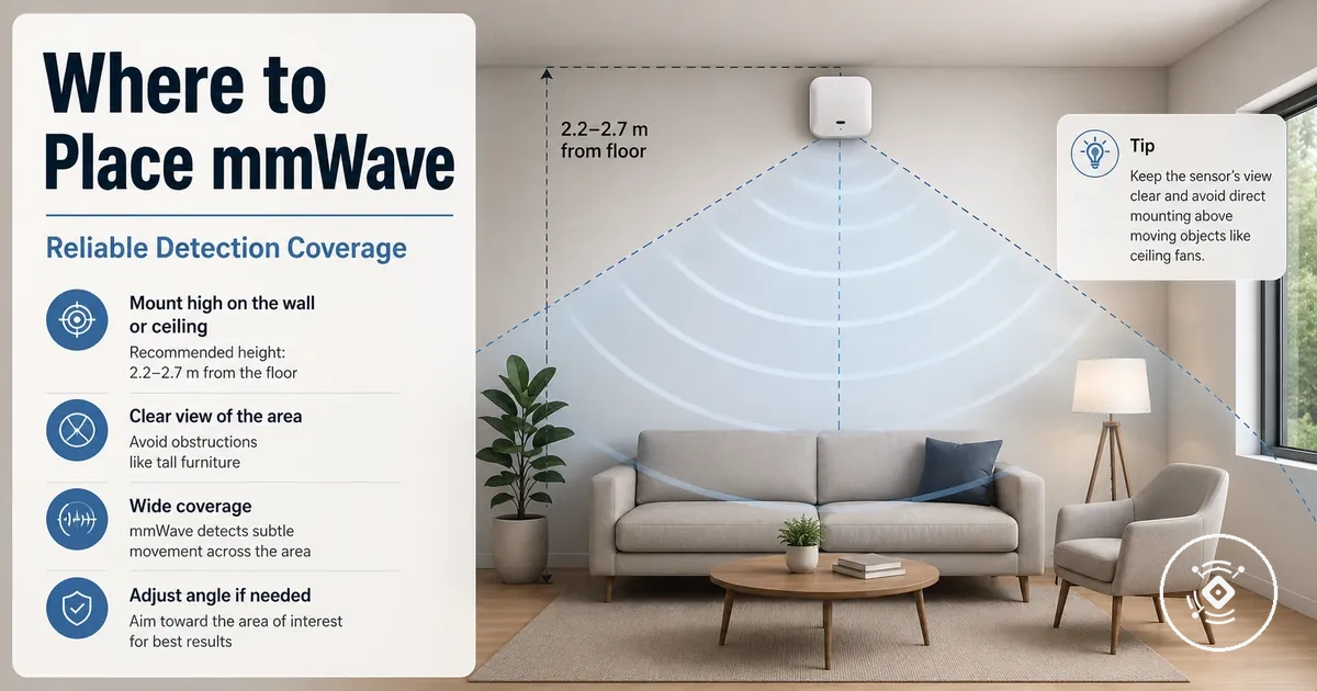
mmWave Presence Sensor Placement for Reliable Room Detection
mmWave presence sensor placement starts with matching the sensor to the occupied area that needs reliable room detection. The detection field should cover normal activity within the intended space while avoiding unnecessary coverage beyond the target area. Room layout, field of view, mount type, sensor angle, and nearby boundaries all influence placement before calibration begins.
Placement is the process of aligning the mmWave presence sensor field of view with the room and its intended detection zone. Mounting height, sensor angle, ceiling mount, wall mount, or flush mount options can change how the coverage area matches seating areas, movement paths, and other occupied spaces. Calibration should follow this placement decision because sensitivity adjustments cannot fully compensate for an unsuitable mount position.
When planning a room, first identify where people are expected to remain or move, then choose a ceiling mount or wall mount that directs the detection field toward those occupied areas. If the sensor faces a doorway, nearby wall, or adjacent room, spillover risk may increase, so the final mount position should keep the detection zone focused on the intended room.
These placement decisions establish the foundation for reliable detection. After the occupied area, field of view, mounting height, sensor angle, and room boundaries have been considered, calibration can be used to refine detection coverage for the specific installation.
How placement changes mmWave detection coverage
mmWave presence sensor placement changes what the detection field can include, so detection coverage depends on sensor position, angle, and the surrounding room. Reliable detection is influenced by where the sensor is aimed, while room layout and nearby objects may affect what the sensor detects or misses.
Sensor position defines how the detection field extends across the room, while angle, range, obstruction, and reflection can change the effective coverage area. Furniture, walls, and other surfaces may alter the detection field, so the final result depends on both the sensor model and the installation environment. A mmWave presence sensor guide introduces the core concepts behind placement before exploring room-specific decisions.
How placement changes mmWave detection coverage is easier to understand with a simple room diagram. The illustration below shows how sensor position, angle, and nearby boundaries shape the detection field and room coverage.
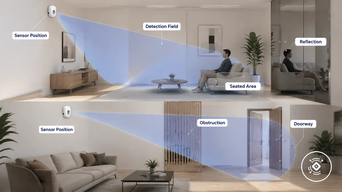
When a sensor is aimed toward a seated area, the detection field can stay focused on the intended occupied area. When it is aimed toward a doorway, movement near the entrance may be included instead, depending on the room layout, range, and sensor settings. This overview prepares you to choose the target room area, while detection zones and sensitivity explain how related settings can further influence room coverage.
- Intended coverage: Detection field directed toward the seated area within the target room.
- Unintended coverage: Detection field extends toward a doorway, which may increase accidental detection or missed presence depending on placement conditions.
Choose the room area the sensor must detect
The target area should be the part of the room where reliable occupancy matters most. Placement decisions should begin with the occupied area because the room area with the highest occupancy value should receive detection priority before a mount location is chosen. The most suitable target area depends on room activity, furniture position, and the intended automation target.
A seating area, desk, bed, or other primary occupied area often deserves higher priority than occasional walking routes. A movement path and an entry path may also be important when room use depends on detecting arrival or regular movement through a doorway. Furniture position and the adjacent boundary should be considered so the detection zone stays focused on meaningful activity rather than nearby spaces that should remain outside the coverage target.
Choose the room area the sensor must detect before selecting a mount position. The annotated layout below identifies priority and exclusion areas to organize placement decisions before installation details.
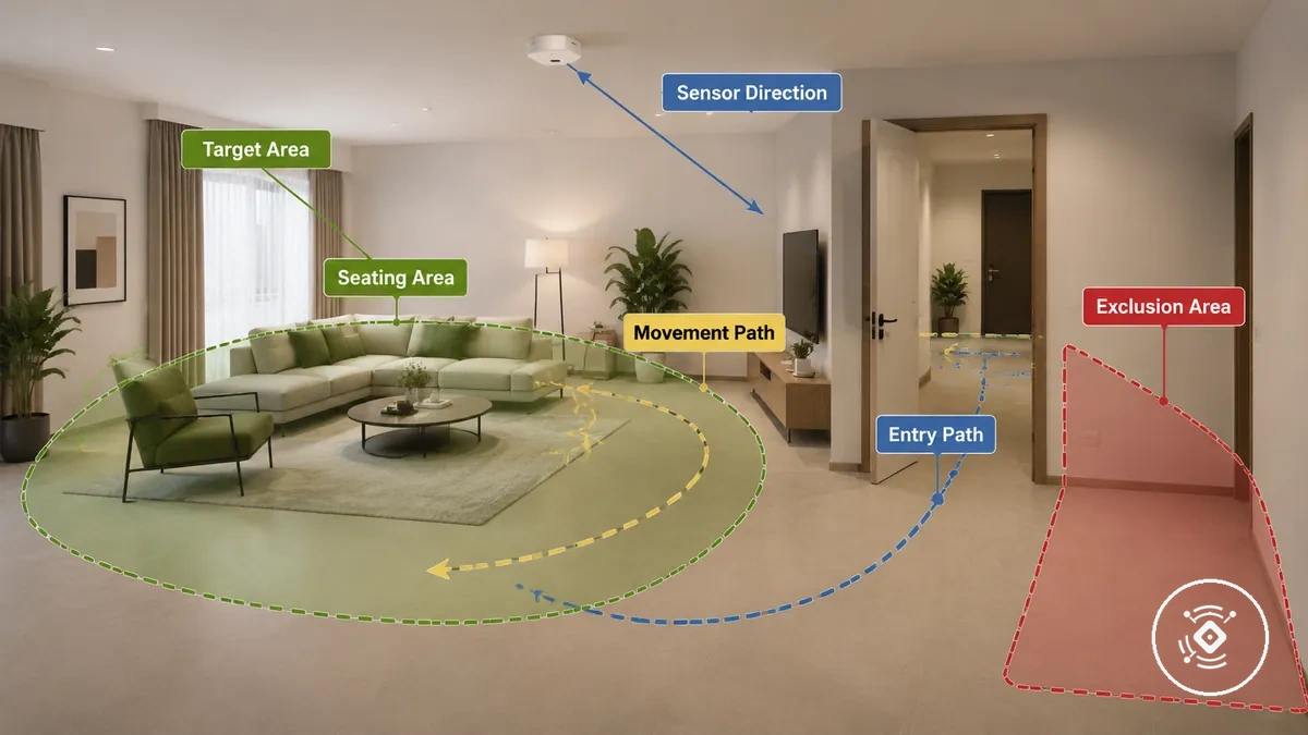
Use this checklist to separate must-detect, may-detect, and should-not-detect areas. The final priority depends on room use, occupancy behaviour, and the automation target.
- Main occupied area: Prioritize the seating area, desk, bed, or other location where occupancy matters most.
- Still-presence point: Include places where occupants may remain seated or stationary for extended periods.
- Movement path: Include common walking routes only when they support the intended room activity.
- Entry path: Include the doorway when entry detection supports the intended automation target.
- Furniture position: Check whether furniture could reduce visibility of the priority area.
- Adjacent boundary: Keep hallways or nearby rooms outside the primary detection zone when they should not influence occupancy detection.
Still presence points and movement paths
When a person spends time working at a desk, relaxing on a sofa, or resting in a bed, that still presence point usually deserves higher placement priority than areas used only briefly. Reliable presence detection may depend on distance, angle, duration, and subtle micro-movement, so missed detection can become more likely when the occupancy point is outside the preferred sensing direction. Still presence points and movement paths create different placement priorities, as illustrated below.
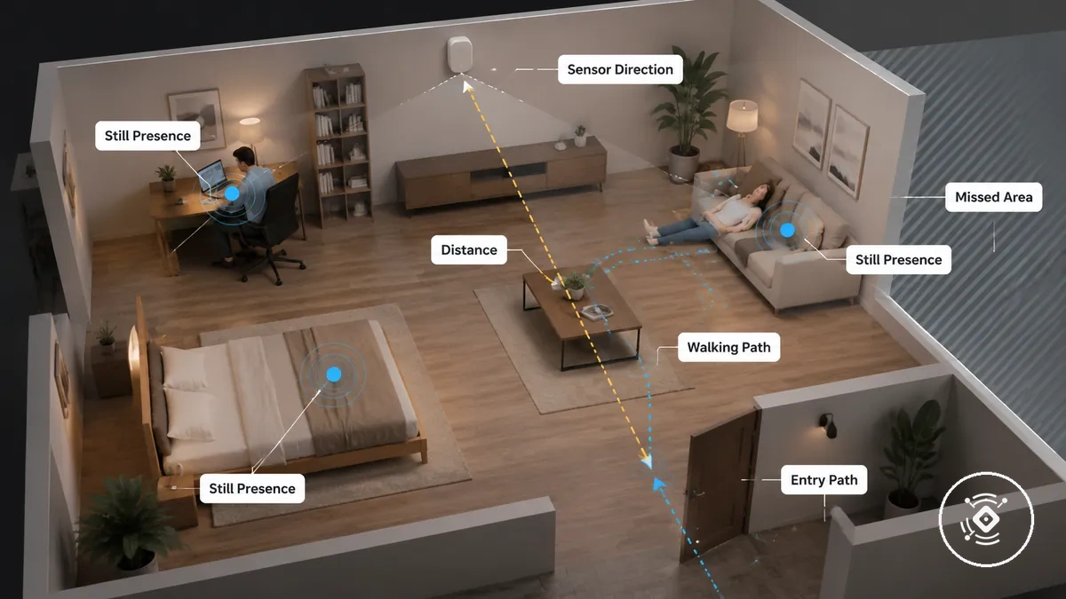
Movement paths deserve attention when regular walking through a walkway or entry path is part of the intended room activity. The examples below distinguish stable occupancy points from movement routes so the local room-area decision can prioritize the position that matters most.
- Seated point: A desk, sofa, or bed used for extended duration often becomes the primary still presence location.
- Standing point: An activity point where someone remains standing may deserve priority when occupancy lasts longer than a brief stop.
- Walking path: A walkway can be included when regular movement supports the intended room use.
- Entry path: A doorway may receive higher or lower priority depending on whether entry events are more important than static presence.
- Overlooked still area: A still presence point at an unsuitable distance or angle may increase the chance of missed detection, so choose whether the stable occupancy point or the movement path deserves priority.
Doors, hallways, and adjacent-room boundaries
Doors, hallways, and adjacent-room boundaries can influence the intended detection area when doorway openness, boundary alignment, or distance allows activity outside the target room to enter the detection field. Spillover risk and false occupancy may become more likely when a doorway or room edge aligns with the sensor direction, so placement should keep the intended detection area focused on the room that matters. Doors, hallways, and adjacent-room boundaries affect detection spillover as illustrated below.
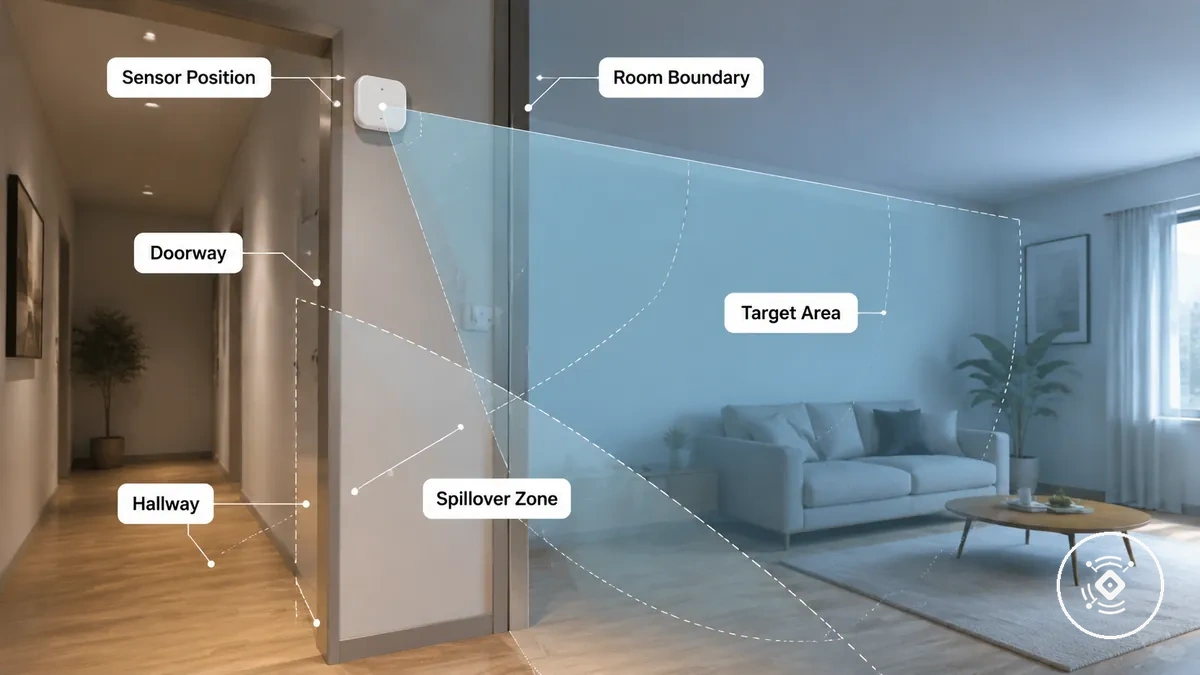
Boundary conditions change which areas should and should not trigger occupancy. The examples below show how doors, hallways, walls, and nearby rooms can influence the intended detection area while keeping unrelated spaces outside the detection boundary.
- Doorway: An open doorway may increase spillover risk when its alignment directs detection toward an adjacent area.
- Hallway: A hallway should contribute to occupancy only when it is intentionally included in the intended detection area.
- Wall: A wall defines the room boundary, although boundary behaviour may vary with layout, distance, sensor direction, material, and settings.
- Nearby room: Activity in a nearby room should usually remain outside the intended detection area when it is not part of the occupancy goal.
If doorway or wall alignment raises questions about adjacent spaces, through-wall detection limits provide additional boundary clarification without assuming nearby rooms should trigger occupancy.
Match the mount type to the detection field
Match the mount type to the detection field by choosing the mounting style that aligns with the room's coverage needs. Mount type affects coverage behavior, while the most suitable placement choice may depend on room geometry, the installation surface, intended occupancy, and the sensor model.
A ceiling mount can provide a broader field of view across an open area, while a wall mount usually offers more directional coverage that can be aimed toward a specific occupied area. A flush mount may integrate with the installation surface, but its fixed position can reduce adjustability and may require greater attention to blind spot risk and coverage limits when making a placement choice.
Match the mount type to the detection field by comparing how each mounting style changes coverage behavior and practical limitations. The comparison below helps relate mount type to room coverage needs instead of treating one option as universally suitable.
| Mount type | Coverage behavior | Placement strength | Main limitation | Best fit condition |
|---|---|---|---|---|
| Ceiling mount | Broad field of view with open coverage from above | Can suit wider room layouts | Blind spot risk may vary with height and room geometry | When broad room coverage is the priority |
| Wall mount | Directional coverage with adjustable aiming | Can focus on a specific occupied area | Coverage depends on angle and placement direction | When targeted detection is preferred |
| Flush mount | Fixed coverage aligned with the installation surface | Clean surface integration | Limited adjustability may increase blind spot risk in some layouts | When the installation surface and room layout support the intended detection field |
After the mount type has been matched to the detection field, continue with installation and setup to refine the mounting approach for the selected placement.
Ceiling placement for open room coverage
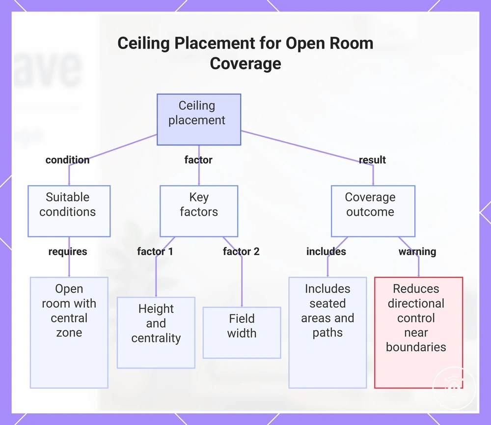
Ceiling placement can suit open room coverage when the sensor needs to observe a broad occupied area from above. This approach may fit an open room with a central activity zone, although the result still depends on room openness, the ceiling position, and the shape of the detection field.
Height, centrality, and field width influence how broadly the sensor covers the room. Broad coverage may include seated areas and walking paths, but it can reduce directional control near walls, doorways, or other boundaries.
This chart shows the conditions, key factors, and coverage outcome of ceiling placement for open room sensor coverage.
Wall placement for directional coverage
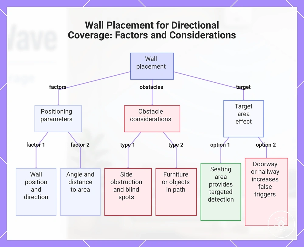
Wall placement fits directional coverage when the sensor needs to focus on a specific occupied area instead of a broader detection field. The effectiveness of targeted detection depends on the wall position, facing direction, angle, and distance to the occupied area, so the outcome may vary with room layout and sensor placement.
Wall placement uses the wall position to direct the detection field toward the intended occupied area while accounting for side obstruction and potential blind spot conditions. Furniture or nearby objects may interrupt the detection field, and aiming toward a seating area can provide more targeted detection than aiming toward a doorway or hallway, where passing traffic may increase unintended occupancy detection.
This chart explains how wall placement directs sensor coverage, the positioning factors that influence effectiveness, common obstacles, and the effect of different target areas.
Flush mount placement and fixed coverage limits
Flush mount placement can work when its fixed coverage matches the room geometry and intended detection field. Reliable coverage depends on whether the fixed angle aligns with the occupied area, so the placement choice should not assume identical behaviour across different flush mounts.
Surface integration can keep the sensor aligned with the mounting surface, but that fixed angle may create a field limitation or constrained coverage when the occupied area falls outside the detection field. If room geometry requires the field to be redirected or adjusted to avoid a blind spot, an adjustable mount may be the more suitable placement choice.
Set mounting height and sensor angle
Mounting height and sensor angle should be adjusted after the mount type has been chosen so the detection field matches the occupied area. The suitable mount height, tilt, and sensor angle depend on the sensor model, room size, ceiling height, and intended detection direction, so detection reliability may require adjustment rather than a fixed placement rule.
Mounting height and tilt work together to shape the field of view and the distance between the sensor and the occupied area. In a small room, a lower or more central aiming position may help keep the coverage field focused, while a larger room or seated occupancy may require a different sensor direction. The appropriate adjustment depends on room geometry and the sensor model.
Manufacturer guidance should be followed when available because recommended mounting height, sensor angle, and height range can vary by model. The table below shows how mounting height and sensor angle organise detection direction and indicate when further adjustment may be needed.
| Placement variable | What to check | Why it matters | Adjustment cue |
|---|---|---|---|
| Mounting height | Distance to the occupied area | Influences the field of view and coverage field | Adjust if the intended area does not receive suitable coverage |
| Sensor angle and tilt | Detection direction | Helps align the detection field with the occupied area | Refine the aiming position within manufacturer guidance |
| Room size | Coverage across the intended space | Different layouts may require different placement | Review the field of view and adjust as needed |
Height by room size and field of view
Room size and field of view should be interpreted together when selecting a mounting height because suitable placement depends on field width, distance to the occupied area, ceiling height, and the sensor specification. A small room and a larger room may require different height ranges, so mounting height should be adjusted to match the intended coverage instead of following a fixed measurement.
Height by room size and field of view is easier to compare using the criteria below. Manufacturer guidance should take priority over these generic examples because sensor specifications may differ. If the resulting detection field does not match the occupied area, review the mounting height and retest after adjustment.
| Room condition | Field-of-view concern | Height cue | Adjustment risk |
|---|---|---|---|
| Small room | Field width may extend beyond the occupied area | Choose a mounting height that keeps coverage focused on the intended space | Retest if coverage extends outside the target area |
| Larger room | Greater distance may reduce effective coverage | A different height range may be needed to maintain suitable field width | Adjust if the occupied area is not fully covered |
| Higher ceiling height | Field width and distance both change | Interpret mounting height according to the sensor specification | Review for adjustment if detection reliability changes |
Direction toward occupied areas
After mounting height is set, aim the sensor toward the occupied area where reliable detection matters. The sensor angle and direction should follow the intended room activity rather than the nearest movement source, because nearby traffic may cause unwanted triggers without improving coverage of the target area.
Check the aiming path for obstruction from furniture or other objects, then keep hallways and unrelated spaces beyond the exclusion boundary when possible. Adjust the sensor angle if the occupied area is missed or unintended movement is detected, but let the intended room activity determine the final direction.
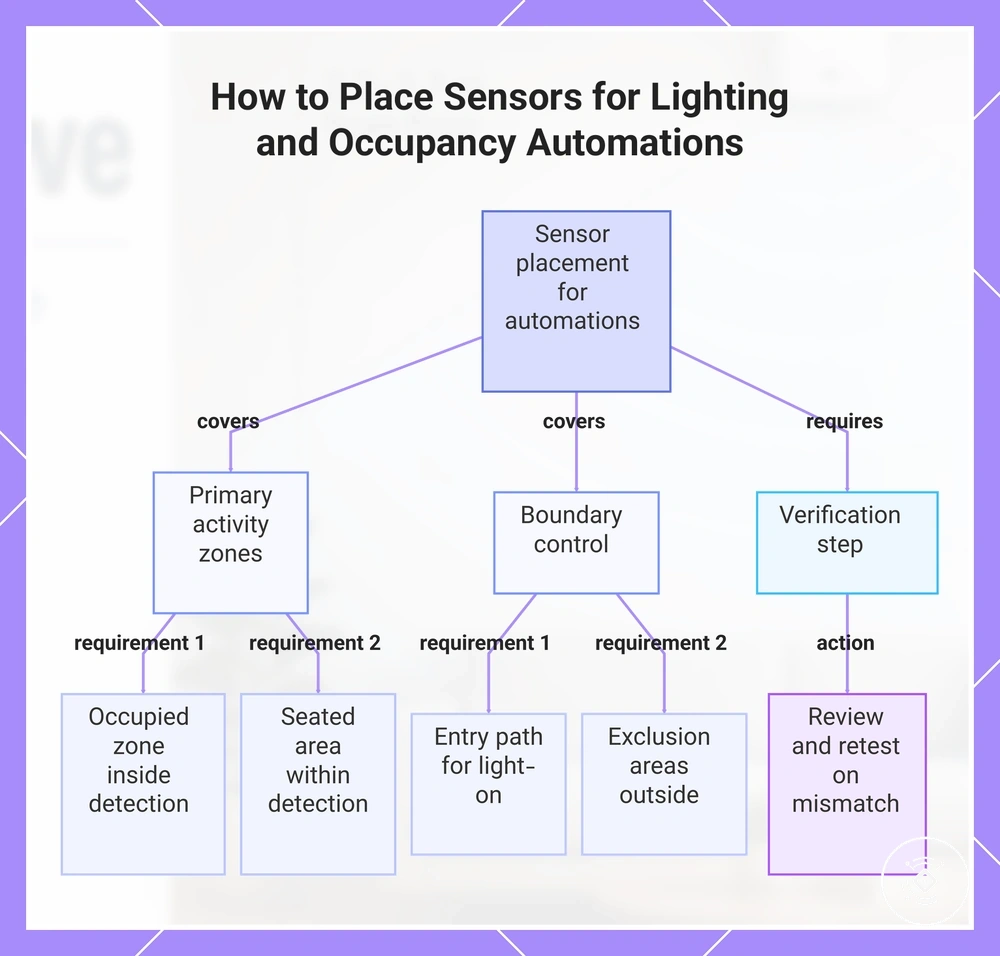
Place sensors for lighting and occupancy automations
Placement for lighting and occupancy automations should match the desired occupancy response because sensor placement determines the occupancy context that the automation receives. Position the sensor around the occupied zone, entry path, and intended room activity so light-on, light-off, and occupancy state changes are based on the areas that matter for the automation use case.
An automation that turns lights on when someone enters may benefit from covering the entry path, while a room used for seated presence may require the occupied zone to remain within the detection zone after movement stops. The appropriate placement depends on room activity, sensor settings, and platform behaviour rather than a universal rule.
Place sensors for lighting and occupancy automations by checking that placement supports the intended automation outcome. Use the checklist below to verify automation-relevant placement, and keep automation behaviour tied to sensor placement rather than app configuration.
- Occupied zone: Keep the primary activity area inside the detection zone so the occupancy state reflects normal room use.
- Entry path: Include the entry path only when it should contribute to a light-on response.
- Seated area: Position the sensor so seated presence can remain within the intended detection zone.
- Exclusion area: Keep nearby rooms or hallways outside the detection zone when they should not influence light-on or light-off behaviour.
- Delay tolerance and retest: If occupancy changes do not match room activity, review placement and retest before changing automation settings.
This chart shows the key placement considerations and verification steps to ensure sensor placement supports the intended automation behavior.
Avoid placement conditions that reduce reliability
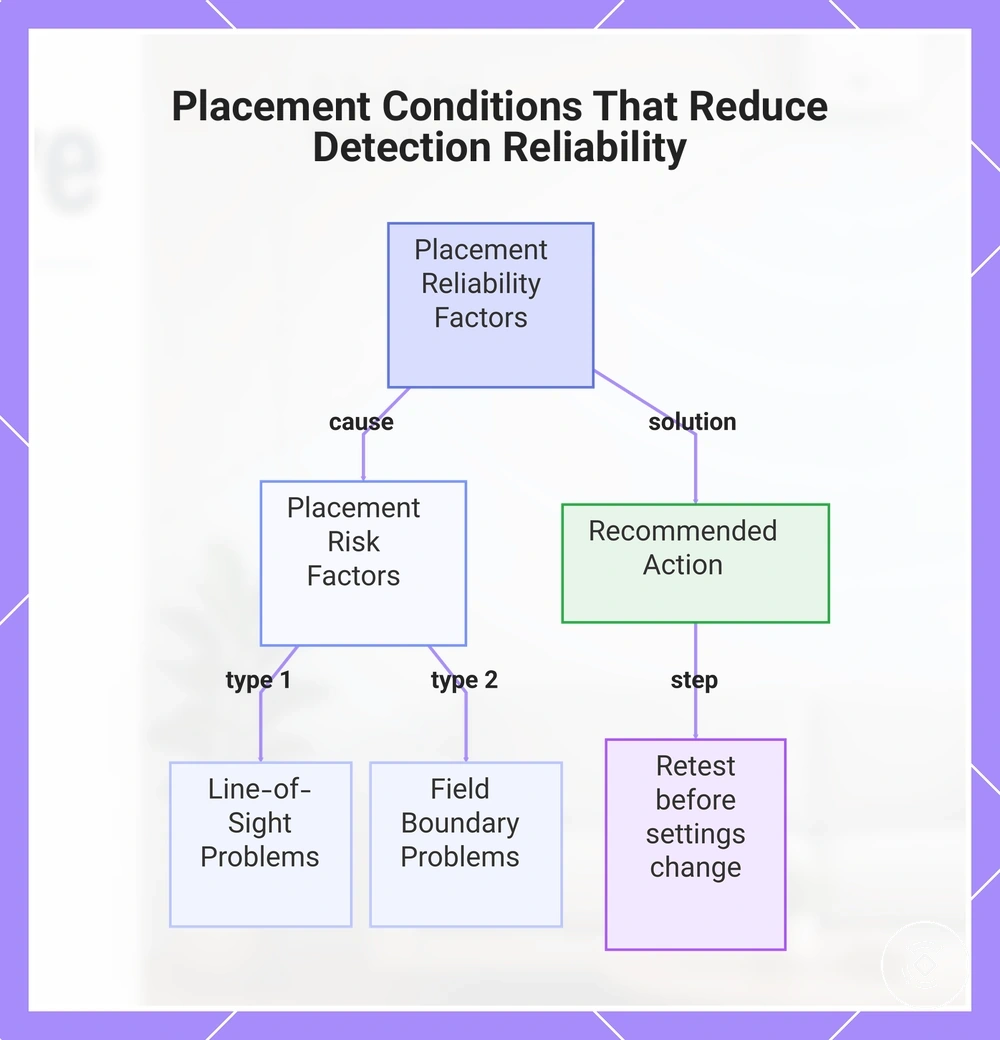
When missed presence, false positives, or unstable occupancy occur, placement conditions may be contributing to the reliability issue, although settings, sensor model, and room material can also influence the result. Check placement before changing settings because a physical positioning issue may continue to affect detection even after software adjustments.
Obstruction, reflection, spillover, excessive field width, and misalignment can each contribute to detection problems under different conditions. These placement conditions may increase missed presence, false positives, or unstable occupancy, depending on the room layout, nearby surfaces, boundaries, model, and settings.
Avoid placement conditions that reduce reliability by using the diagnostic checklist below to identify placement-specific risks before adjusting settings. The checklist focuses only on placement causes that may reduce detection reliability.
- Obstruction: Check whether furniture or other objects block the detection path to the occupied area.
- Reflection: Consider whether nearby surfaces may be redirecting detection toward unintended areas.
- Spillover: Check whether the detection field extends into an adjacent room or another unintended boundary.
- Excessive field width: Review whether the detection field covers more space than the intended activity area requires.
- Misalignment and nearby movement: Confirm that the sensor remains aimed at the intended occupied area rather than nearby movement that could contribute to false positives.
- Retest: After adjusting placement, retest detection reliability before changing settings so the effect of the physical adjustment can be evaluated.
If placement-specific checks do not resolve the issue, continue to troubleshoot detection problems for broader diagnostic guidance.
This chart shows the main placement risk factors that can cause missed presence, false positives, or unstable occupancy, and the recommended action to retest after adjustment.
Blocked or reflective detection paths
When reduced detection occurs, a blocked path may be caused by an obstruction between the sensor and the occupied area. The object's position, material, and angle can affect the detection path, so reposition the object or adjust the sensor aim when furniture, an appliance, or another obstacle appears to interrupt coverage.
A reflective path may contribute to reflected detection or inconsistent occupancy when a nearby surface redirects part of the detection field. The effect can vary with surface material, position, room layout, sensor model, and angle, so avoid assuming every reflective surface behaves the same and retest after repositioning or re-aiming the sensor.
Detection spillover through doors, walls, or nearby rooms
Detection spillover can occur when the detection field extends beyond the intended placement boundary into doors, walls, or nearby rooms. This may contribute to adjacent-area detection or false occupancy, although the outcome can vary with sensor direction, room layout, model, and sensitivity context.
A doorway opening, wall proximity, or sensor direction may increase spillover toward a hallway or nearby room when the field is not sufficiently contained. Repositioning or re-aiming the sensor may reduce the boundary problem, but settings adjustment can still be needed if placement changes alone do not sufficiently limit false occupancy.
Over-wide zones and false positives
When over-wide zones extend beyond the intended area, false positives may occur because the sensor includes movement that is not part of the target coverage. Narrower aiming through placement adjustment can often reduce false positive risk before changing calibration settings.
Zone width may include adjacent paths, pets, moving surfaces, or other unintended movement sources that increase unwanted triggers. Review what the broad field is capturing, then decide whether narrower aiming is needed before adjusting calibration settings.
Over-wide zones and false positives can be diagnosed by checking whether the detection field includes unintended movement sources:
- An adjacent path, doorway, or hallway may fall within the zone width and increase false positive risk.
- A pet area may contribute to unwanted triggers when it is included in excessive coverage.
- Moving surfaces may affect detection when they remain inside the broad field.
- Boundary spillover beyond the intended area may indicate that narrower aiming should be tried before changing calibration settings.
Check placement before calibration and setup
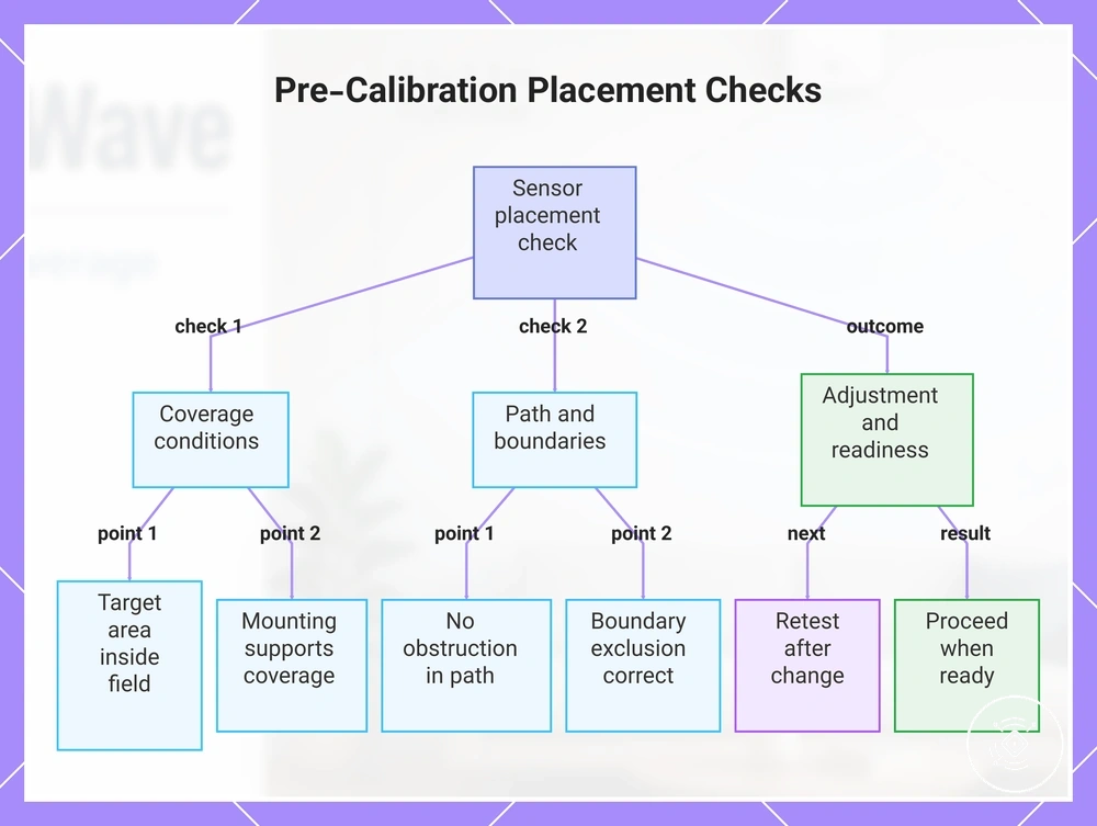
Placement should be checked before calibration and setup. This placement check confirms whether the sensor is ready for the next stage or still needs adjustment.
Verify that the target area remains inside the intended detection field and that the mount type suits the room layout. Adjust the placement if either condition does not support the required coverage.
Confirm that the mounting height and direction keep the occupied area within the detection field. Retest after any change to height or direction before proceeding.
Review boundary exclusion and check for any obstruction that may interrupt detection or include unintended areas. Correct these placement issues before treating them as calibration problems.
- Confirm the target area is inside the intended detection field.
- Verify that the mount type suits the room layout.
- Check that the height supports the required coverage.
- Confirm that the direction aligns with the occupied area.
- Review boundary exclusion for unintended detection.
- Check for an obstruction in the detection path.
- Confirm that placement supports the intended automation need, if applicable.
- Retest after any placement adjustment.
Proceed when the placement check supports the intended coverage; otherwise, adjust and retest. Once placement readiness is confirmed, continue with calibration after placement.
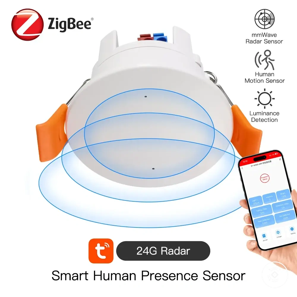
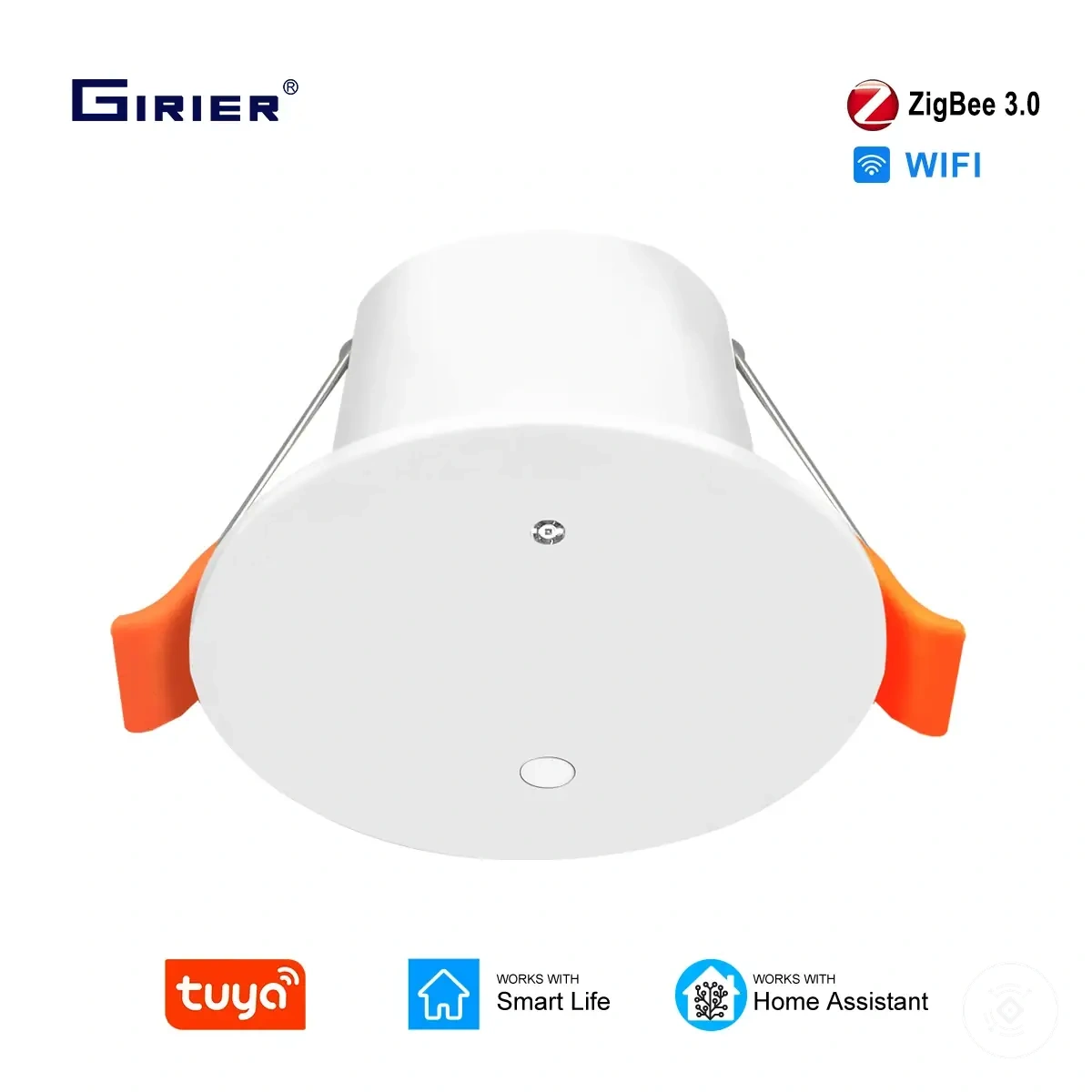
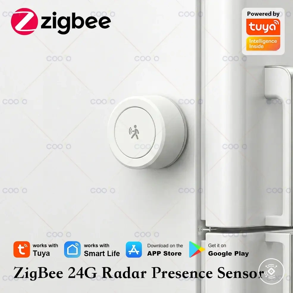
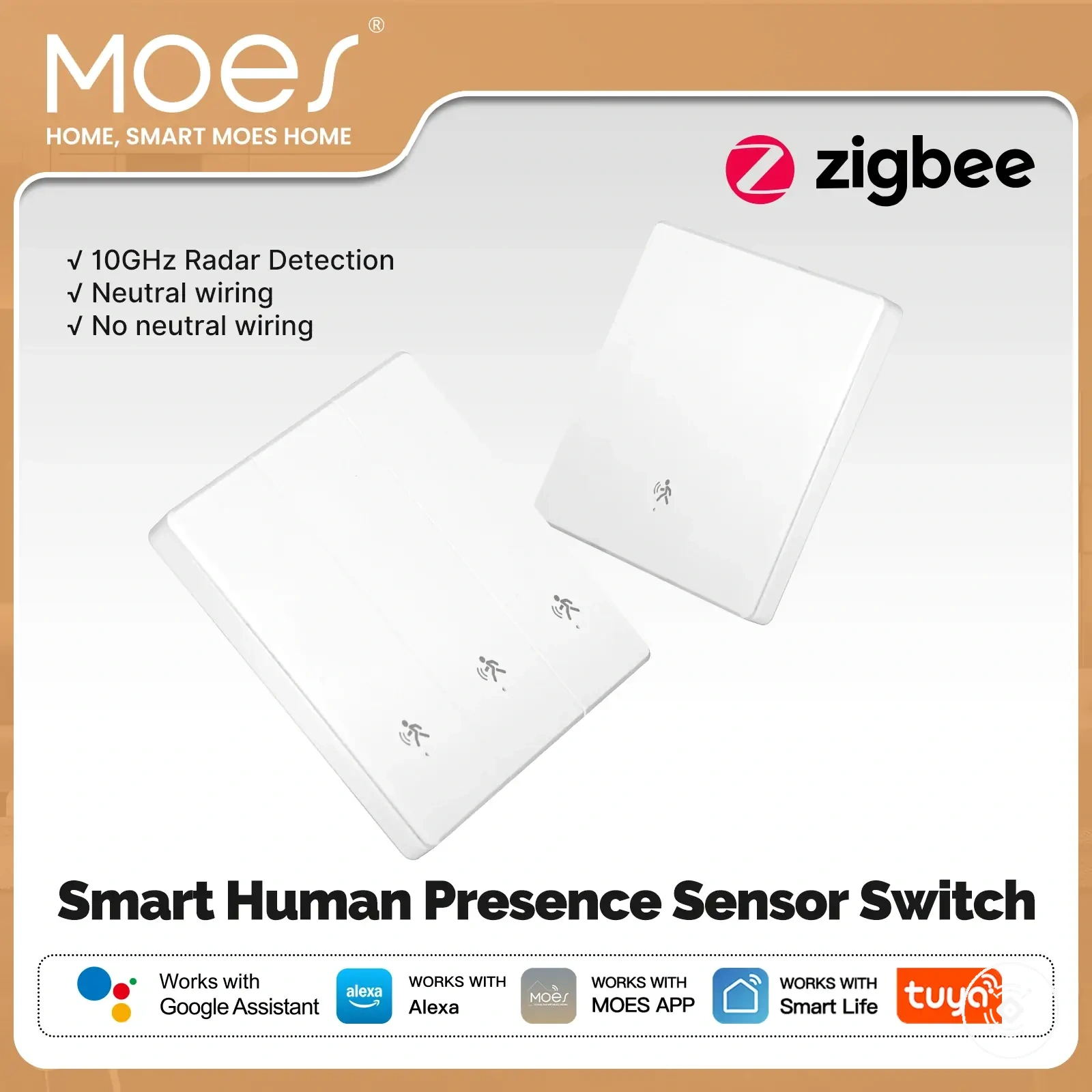
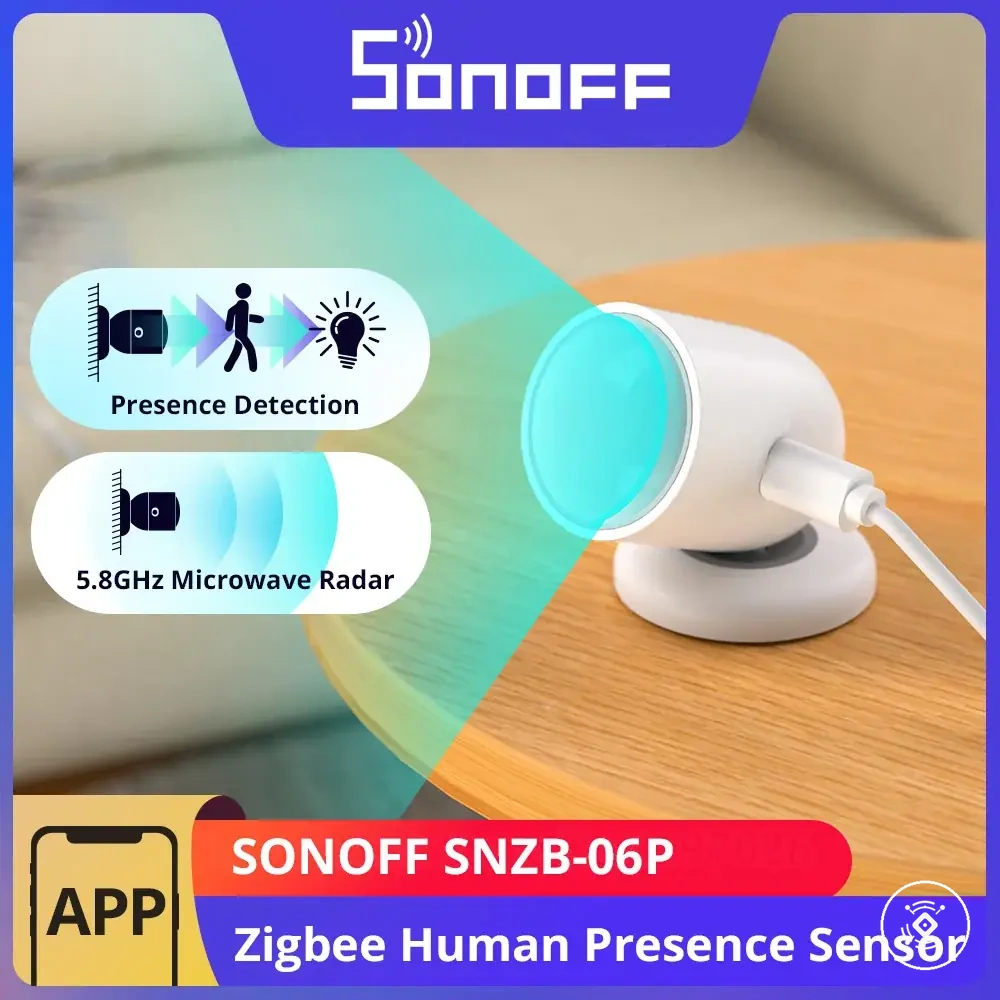
Here are product examples that may make comparison easier. Before buying, always review the compatibility criteria, essential features, and product details.
This chart outlines the essential placement checks to verify sensor readiness before calibration, along with the adjustments required when conditions are not met.