
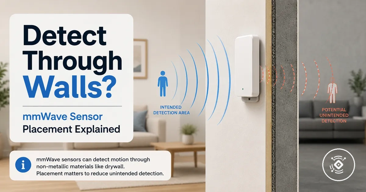
mmWave presence sensor wall penetration and detection limits
A mmWave presence sensor may detect beyond walls in some situations, but the outcome depends on conditions such as wall material, detection zone design, sensitivity, and placement. Wall penetration is not a fixed capability that applies the same way to every sensor. The detection result can range from reduced signal, partial detection, or unintended detection near an adjacent room depending on the environment.
A mmWave presence sensor guide explains the broader role of radar-based presence sensing, while this page focuses on wall penetration and detection limits. A mmWave presence sensor uses radar signal behavior to identify presence-related changes, and walls can influence how that signal travels, reflects, or loses strength. The final detection outcome depends on the relationship between the sensor, the wall material, the detection zone, and the surrounding space.

A sensor placed near a room boundary may interact with areas outside the intended space depending on the wall structure and sensor configuration. In some cases, signal behavior around a boundary can contribute to adjacent room detection concerns. This does not mean a sensor can reliably detect through every wall, because normal signal interaction and false occupancy risks depend on different conditions.
Users often want to know whether a wall will block detection or allow unwanted detection beyond the room. The answer depends on how the wall affects the radar signal and how the sensor is positioned. Factors such as material, distance, sensitivity, detection zone, and mounting direction shape the possible detection outcome.
- Wall material: Different materials can change signal attenuation, reflection, and possible detection behavior.
- Detection distance and zone: The size and design of the detection area may influence boundary-related detection.
- Sensitivity: Sensitivity settings may affect how the sensor responds to weaker signals.
- Placement: Mounting direction and wall distance can influence detection boundaries.
How mmWave presence sensing behaves around walls
mmWave presence sensing around walls depends on how the radar signal interacts with nearby surfaces and boundaries. A mmWave presence sensor can experience changes in signal behavior when walls are present, including reflection, attenuation, and changes to the detection field. The outcome depends on conditions such as the wall, field of view, and sensor design rather than a fixed ability to detect beyond a barrier.
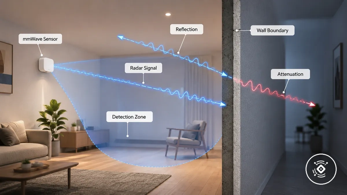
A sensor placed near an interior wall may interact with a room boundary outside the intended detection area. The radar signal can reflect from nearby surfaces or become weaker as it encounters obstacles, which may change how the sensor responds in that space. These effects can influence rear response or side response depending on model variation, mounting conditions, and detection behavior. Reflection and attenuation describe different ways a radar signal may change around walls.
Wall interaction does not mean a mmWave presence sensor provides guaranteed detection through a barrier. A wall can influence radar signal behavior, but detection beyond the intended area depends on factors such as sensitivity, field of view, model variation, and surrounding conditions. These differences help separate normal signal interaction from possible boundary-related detection before considering how material properties affect the result.
Materials that allow or block mmWave detection
Wall material, thickness, and conductivity can change how mmWave detection behaves around a barrier. A mmWave presence sensor may experience different signal effects depending on whether a material allows more signal interaction, reduces signal strength, or reflects radar energy. These material conditions affect the likelihood of wall-side detection, but they do not create fixed penetration or blocking rules for every sensor.

Wall material behavior describes how a barrier interacts with the radar signal. Lower-density materials such as drywall or plasterboard may behave differently from dense walls, while metal and foil-backed insulation can interact with signals through conductivity and reflection. The detection outcome depends on material properties, thickness, sensitivity, and device variation rather than the material name alone.
The table below compares common wall materials and barriers by their relevant attributes, likely signal behavior, and possible detection implications. These examples describe general tendencies rather than exact pass or block results.
| Material or barrier | Relevant attribute | Likely signal behavior | Detection implication |
|---|---|---|---|
| Drywall or plasterboard | Lower-density partition material | May allow partial signal interaction depending on thickness and conditions | Wall-side detection can vary with sensitivity and placement |
| Glass or plastic | Non-metallic material | May create different attenuation effects depending on construction and thickness | Detection behavior can vary by sensor conditions |
| Plywood | Material density and thickness | Signal interaction may change with layers and surrounding conditions | Possible detection outcomes depend on the sensor environment |
| Brick or concrete | Dense wall material | May reduce signal strength through greater attenuation | Detection beyond the barrier may become less likely depending on conditions |
| Metal or foil-backed insulation | Conductivity and reflective surface behavior | May reflect or reduce radar signal interaction | Detection response can change based on arrangement and sensor position |
Material comparisons help explain why different barriers can create different detection outcomes. The final behavior still depends on factors such as thickness, sensor sensitivity, detection zone design, and the surrounding environment.
Thin non-metallic materials
Thin non-metallic materials may allow partial signal interaction depending on their thickness, layering, and sensor conditions. Materials such as drywall, plasterboard, plastic, glass, and thin wood can affect attenuation and radar signal behavior in different ways. The detection outcome depends on the barrier thickness and the mmWave presence sensor sensitivity rather than the material category alone.
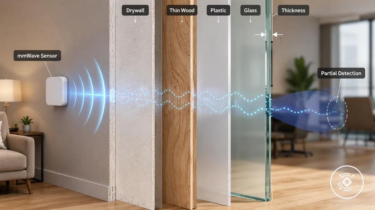
A sensor near an interior partition may experience different detection behavior when the barrier is made from a light, low-density material. A thin drywall or plastic partition may create different signal interaction than a denser barrier, but partial detection beyond the material can vary with thickness, sensitivity, and surrounding conditions.
Dense walls and metallic barriers
Dense walls and metallic barriers usually reduce, block, or redirect mmWave signals depending on their density, conductivity, structure, and position relative to the sensor. Concrete, brick, stone, metal, and foil-backed insulation can create different levels of attenuation or reflection, but the result depends on factors such as gaps, angle, and device variation.
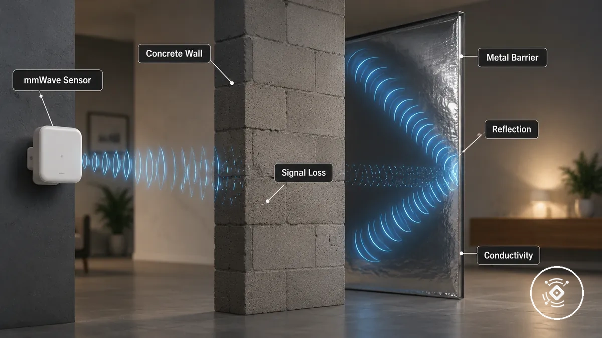
Signal loss and reflection are different effects that can occur around dense or conductive barriers. A metal surface may reflect radar energy, while a dense wall may reduce signal strength through attenuation. This does not mean every barrier completely blocks detection, because surrounding conditions and sensor behavior can change the outcome.
- Concrete, brick, and stone: Higher-density materials may increase attenuation and reduce signal interaction depending on thickness and conditions.
- Metal surfaces: Conductive barriers may reflect or redirect radar signals rather than simply reducing them.
- Foil-backed insulation: Conductive layers may influence signal behavior and create different detection conditions.
Detection distance and signal strength through barriers
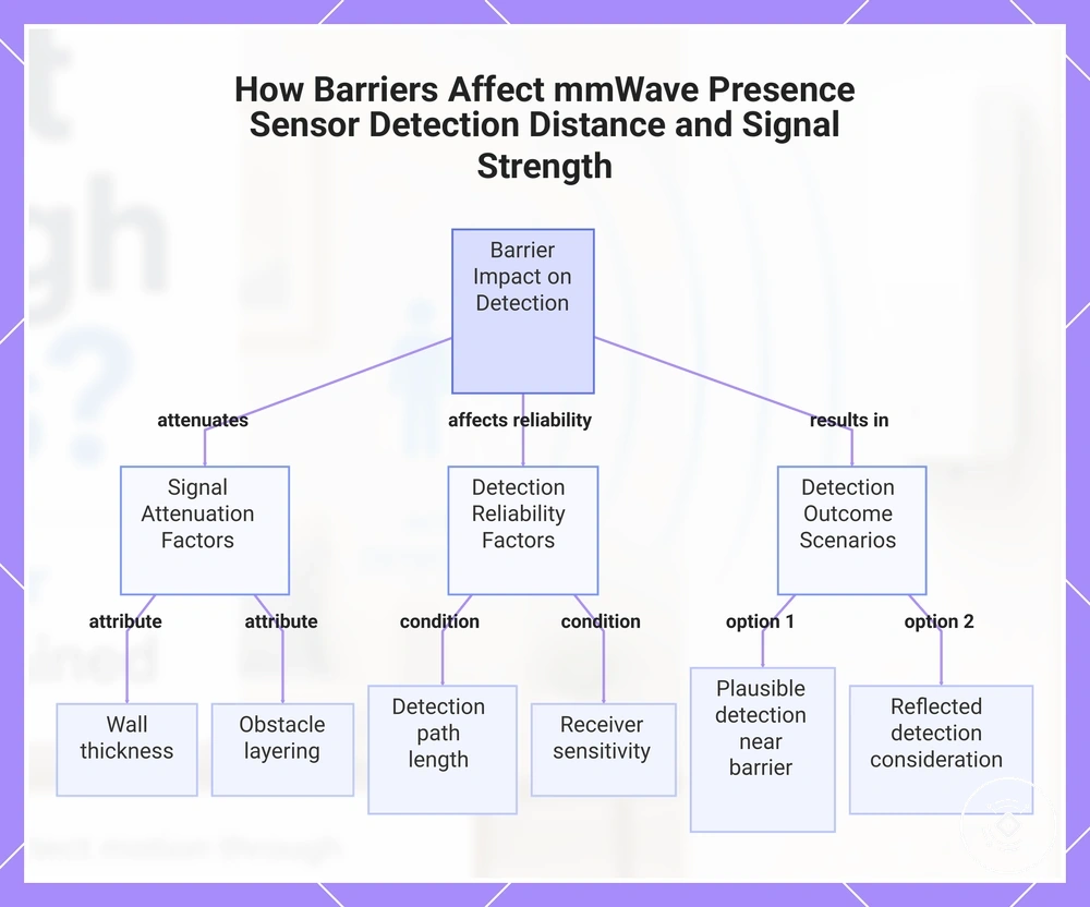
Detection distance and signal strength through barriers depend on how a mmWave presence sensor interacts with the barrier between the sensor and the detection area. A wall or obstacle can reduce signal strength through attenuation and may affect detection reliability compared with an open path. The outcome depends on conditions such as wall thickness, distance, sensitivity, and sensor design.
The relationship between barriers and detection distance is shaped by several attributes. Wall thickness, obstacle layering, and longer signal paths can influence signal level, while frequency, transmit power, receiver sensitivity, room size, and surrounding surfaces may change detection behavior. A presence reading near a barrier may be a plausible detection condition or may require consideration of reflected detection and environmental factors.
These conditions can help explain how detection distance and signal strength through barriers may change:
- Wall thickness: Thicker barriers may increase attenuation and reduce available signal strength depending on the material and conditions.
- Distance to the person: A longer detection path may influence detection reliability and signal level.
- Receiver sensitivity: Sensor sensitivity can affect how weaker signals are interpreted.
- Obstacle layering: Multiple barriers may create different signal behavior compared with a single barrier.
- Detection zones: The relationship between range and detection zones and barrier conditions can help explain possible detection outcomes.
This chart shows the key factors that influence detection distance and signal strength when a mmWave presence sensor operates behind a barrier, and the possible detection outcomes.
Why a sensor may detect another room
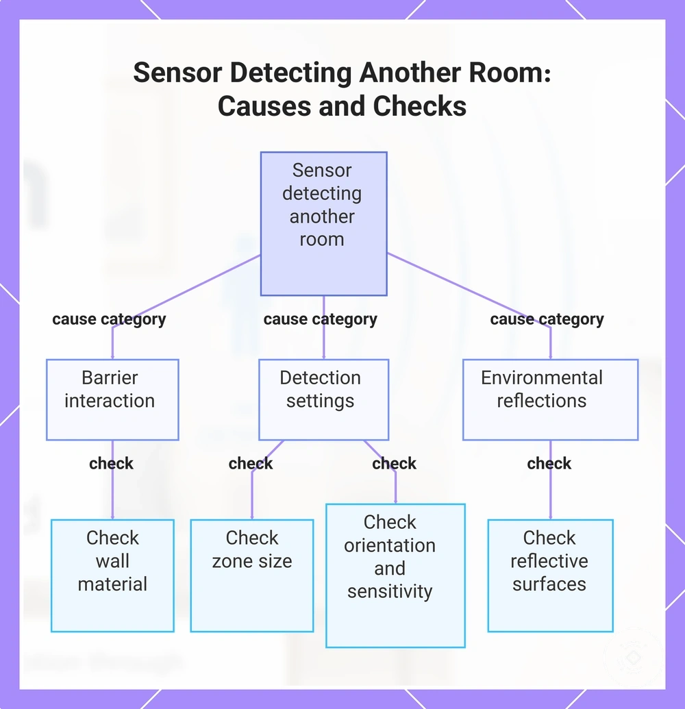
A mmWave sensor may detect another room when conditions such as wall material, zone size, sensitivity, mounting angle, or reflections allow unintended detection near a room boundary. Multiple causes can create similar adjacent room reports, so another-room detection alone does not confirm a specific fault. The result depends on the interaction between the sensor, the environment, and the room boundary.
A sensor reporting presence outside the intended area may be related to direct penetration, oversized zones, rear-side sensitivity, or reflected detection from nearby surfaces. Wall material can influence signal behavior, while sensitivity and mounting angle can change the detection boundary. Separating these causes helps identify whether the condition is linked to barrier interaction, detection settings, or surrounding objects.
The following checks can help separate the likely causes of another-room detection:
- Direct penetration: If detection appears near an adjacent room, check whether the wall material and barrier conditions may allow signal interaction beyond the intended area.
- Zone size: If the detection area extends past the room boundary, check whether the configured detection zone is wider than the intended space.
- Reflections: If detection occurs near reflective surfaces, check whether nearby objects or materials may redirect the radar signal.
- Rear-side sensitivity: If detection occurs behind or beside the sensor, check the sensor orientation and sensitivity conditions.
- Mounting angle: If the sensor faces toward a room boundary, check whether the angle changes the intended detection field.
This chart shows the main cause categories and corresponding checks to identify why a mmWave sensor may detect presence in an adjacent room.
Direct penetration versus reflected detection
Direct penetration and reflected detection describe two different signal paths that can lead to similar detection results near a wall. A mmWave sensor may detect beyond an intended boundary because a signal interacts with a barrier or because reflection changes the detection field. The main comparison is whether the signal passes through a material or reflects from nearby surfaces.
The difference between these paths depends on the surrounding conditions. Direct penetration may be associated with wall material and attenuation, while reflected detection may be influenced by nearby surfaces, sensitivity, and zone boundaries. Observing when and where detection changes can provide a safer next check before identifying the likely cause.
| Detection path | Observable clue | Likely cause | Next check |
|---|---|---|---|
| Direct penetration | Detection remains near the same wall boundary | Signal interaction with the wall material or barrier conditions | Check the wall, material, and sensor sensitivity conditions |
| Reflected detection | Detection changes when nearby surfaces or objects change | Signal reflection from surrounding materials or surfaces | Check reflective surfaces, zone boundaries, and nearby objects |
Rear-side and side-wall detection behavior
Rear-side and side-wall detection behavior can occur when a mmWave sensor detects beyond its intended forward-facing zone due to sensor design, orientation, or surrounding conditions. Wall proximity, corner placement, and sensitivity can influence detection boundaries, but rear or side response varies by device design. The outcome depends on how the sensor signal interacts with the wall, material, and nearby environment.
A mmWave sensor near a wall or corner may show different detection behavior when signal paths, reflection, attenuation, and detection zones change. Sensor orientation can affect which areas are included in the detection field, while housing design, side response, or rear sensitivity may influence boundary behavior on some devices. Understanding these attributes helps explain unexpected detection without assuming every sensor has the same response pattern.
- Wall proximity: Detection close to a wall may change when the signal interacts with nearby surfaces or barriers.
- Corner placement: A corner position may influence the detection field because surrounding walls can affect signal behavior.
- Sensor orientation: The direction of the sensor may change which areas fall within the expected detection zone.
- Sensitivity: Sensitivity conditions may affect how weaker signals near boundaries are interpreted.
Settings that control detection near walls
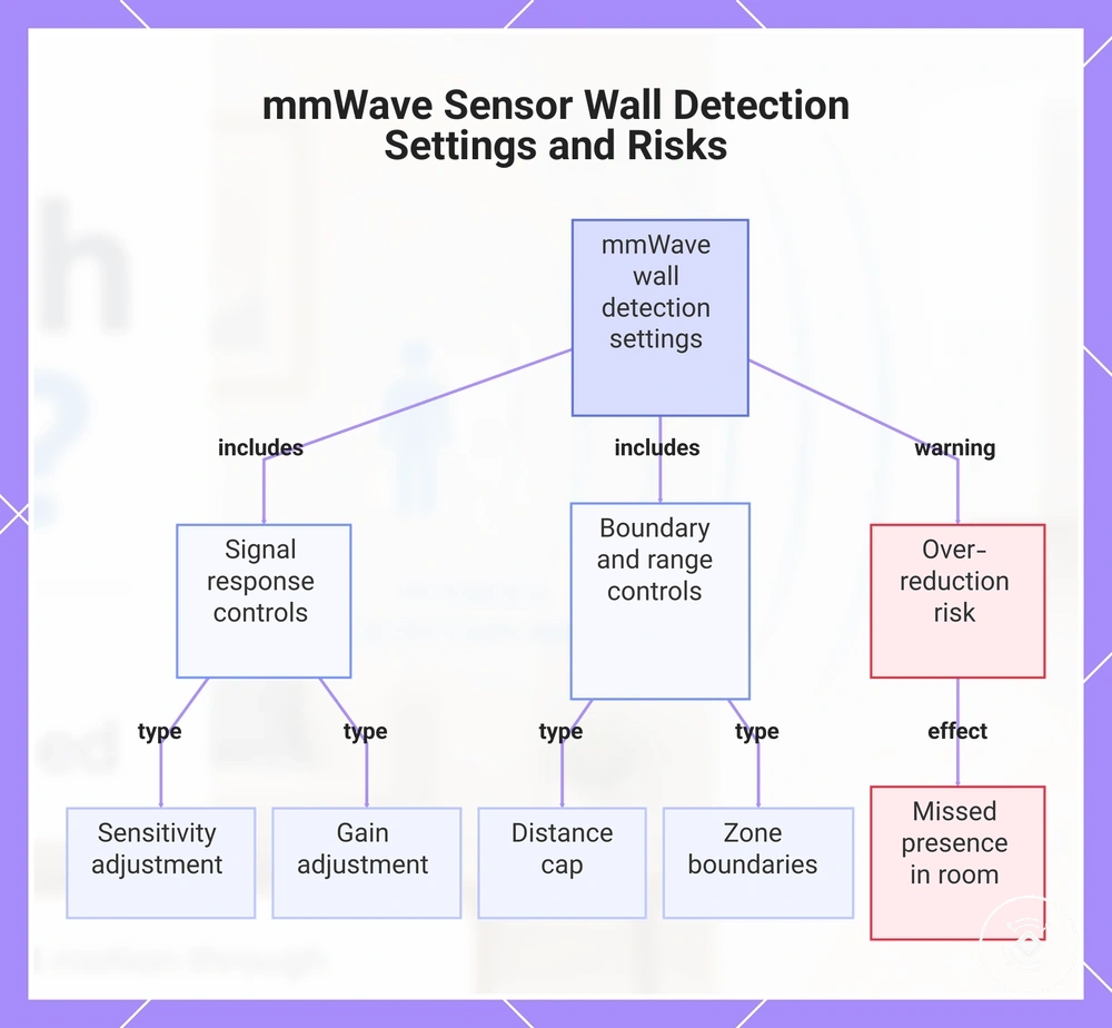
Settings that control detection near walls can influence how a mmWave sensor responds near boundaries, but they do not provide guaranteed fixes for every unintended detection condition. Sensitivity, gain, distance cap, and zone boundaries can change how the detection field is interpreted depending on the sensor configuration. The effect depends on the device, environment, and the need to balance wall-side detection with reliable room coverage.
Configuration settings affect detection by changing how signals near walls are handled. Sensitivity and gain can influence weaker signal responses, while distance cap and zone boundaries can help limit the detection area when those controls are available. Detection delay, hold time, exclusion zones, and calibration options may also affect how presence is evaluated. Reducing these settings too aggressively can create missed presence inside the intended room.
Common settings that may influence detection near walls include:
- Sensitivity: A sensitivity level change may reduce responses from weaker signals near boundaries, but it can also affect subtle presence detection.
- Gain: Gain adjustments can change how signal strength is interpreted, depending on the sensor design and surrounding conditions.
- Distance cap: A range limit may reduce detection beyond a preferred area when supported, but the effect depends on the available configuration.
- Zone boundaries: Zone controls may help define the intended detection field and reduce unwanted wall-side detection.
- Detection delay and hold time: Timing settings can influence how long a presence state remains active after detection.
- Exclusion zones and calibration: These controls may help manage specific areas, but their availability and behavior depend on the device or app limitations.
This chart shows the main settings that influence detection near walls and the risk of overly reducing them.
Sensitivity, distance limits, and zone boundaries
Sensitivity, distance limits, and zone boundaries control how a mmWave sensor responds near walls by changing the detection field and the way signals are evaluated. These settings can influence wall-side detection, but their effect depends on the device configuration and surrounding conditions. The goal is to reduce unwanted detection while maintaining reliable presence detection inside the intended area.
Each control affects a different detection attribute. Sensitivity or gain changes can influence weaker signals, distance caps can limit the detection range when available, and zone boundaries or exclusion zones can define where detection is considered relevant. Hold time, detection delay, and calibration options can affect how long presence remains active. These settings involve trade-offs because reducing detection too aggressively can increase missed presence.
| Setting | Value change | Benefit | Risk |
|---|---|---|---|
| Sensitivity or gain | Lower sensitivity or gain levels may reduce response to weaker signals | May reduce wall-side detection in some conditions | Can increase missed presence inside the intended area |
| Distance cap | A shorter range limit may reduce the detection field | May help limit detection near distant boundaries | Can reduce valid detection farther inside the room |
| Zone boundaries or exclusion zones | Smaller defined areas can change where detection is evaluated | May reduce unwanted responses near specific boundaries | Effect depends on available configuration options |
| Hold time and detection delay | Timing changes affect how presence states are maintained | Can influence how repeated signals are interpreted | May change responsiveness depending on the use case |
Placement choices that reduce detection beyond the room
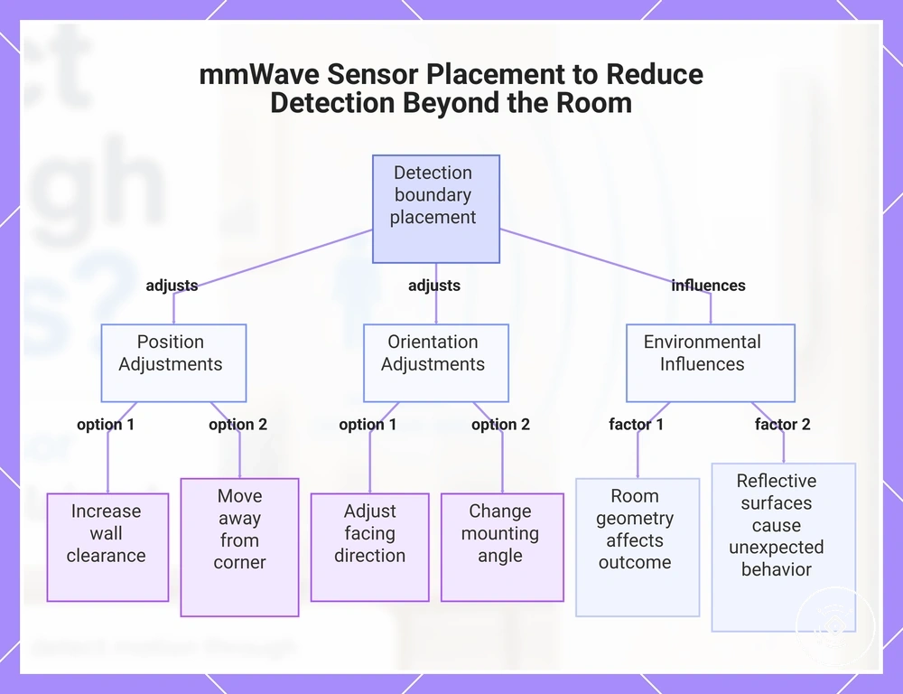
Placement choices that reduce detection beyond the room matter when a mmWave sensor detects near a wall, corner, or boundary outside the intended occupied area. The sensor position, mounting angle, facing direction, and wall distance can influence the detection boundary, but placement changes may also affect coverage of the occupied area. The result depends on the room geometry, sensor design, and surrounding conditions.
Physical placement changes how the detection field interacts with walls and nearby surfaces. Increasing wall distance, adjusting mounting angle, or changing facing direction may reduce wall-side detection in some situations, while corner placement and reflective surfaces can influence reflections and detection behavior. A practical approach is to consider the intended occupied area first and then evaluate whether the boundary response changes.
- Wall distance: If the sensor is close to a wall, increasing wall clearance may reduce boundary interaction, but it can change coverage of the occupied area.
- Facing direction: If the sensor points toward a boundary, adjusting the facing direction may help align the detection field with the occupied area.
- Corner placement: If the sensor is near a corner, changing the position may reduce interaction with multiple nearby surfaces, but room geometry affects the outcome.
- Mounting angle: If the angle directs detection toward a boundary, adjusting the mounting angle may change the detection boundary, depending on the device.
- Reflective surfaces: If nearby surfaces influence signal reflection, considering their location may help explain unexpected detection behavior.
Placement decisions involve a balance between limiting detection beyond the room and maintaining reliable coverage. For broader guidance on physical positioning factors, see sensor placement and mounting. Placement changes can influence detection boundaries, but they should not be treated as a guaranteed solution for every environment.
This chart shows the key placement adjustments and environmental factors that influence mmWave sensor detection boundaries outside the intended occupied area.
Wall distance, mounting angle, and facing direction
Wall distance, mounting angle, and facing direction matter when a sensor is positioned near a wall where the detection boundary may extend beyond the intended area. These placement attributes can influence how the sensor field aligns with the occupied area and nearby surfaces. The effect depends on the room geometry, sensor design, and surrounding conditions rather than a fixed placement rule.
Placement choices can be evaluated by considering how each geometry variable changes the detection field:
- Wall distance: If the sensor has limited wall clearance, increasing the wall distance may reduce boundary interaction, but it can also change coverage of the occupied area.
- Mounting angle: If the mounting angle directs the sensor field toward a wall or boundary, adjusting the angle may change detection behavior depending on the environment.
- Facing direction: If the sensor face direction does not align with the occupied area, changing the facing direction may help match the detection field to the intended space.
- Height and corner placement: If the sensor is positioned near a corner or at a different height, room geometry and nearby walls may influence the detection boundary.
- Reflective surfaces: If nearby reflective surfaces influence signal reflection, their position may contribute to changes in detection behavior.
These geometry factors involve balancing reduced detection beyond the room with reliable coverage of the occupied area. Placement changes should be considered as local adjustments rather than universal solutions, because wall clearance, sensor position, and room geometry can produce different outcomes.
Physical blocking and shielding options
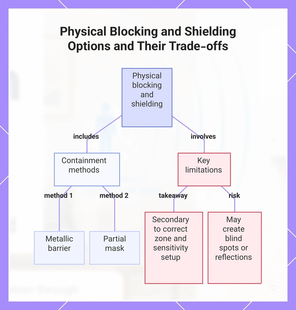
Physical blocking and shielding options matter when settings and placement changes have been considered but detection beyond the intended room remains a concern. These approaches can help contain signal interaction near a boundary, but they are not guaranteed solutions for every environment. Physical blocking should be treated as a containment tactic rather than a replacement for correct detection zone and sensitivity setup.
Potential containment approaches should be considered carefully because changing the signal environment can create new effects. Options may influence signal reduction, reflection, or the detection boundary depending on the surrounding conditions.
- Metallic barrier: If a conductive barrier is introduced near a boundary, it may influence signal behavior and containment, but it can also create reflection-related changes.
- Foil-backed material: If a foil-backed material is considered as a barrier layer, it may affect signal interaction in some conditions, but the result depends on the overall setup.
- Partial mask: If a partial mask is used to limit part of the detection field, it may improve containment while creating a risk of a blind spot.
- Enclosure changes: If the surrounding enclosure is altered, the change may affect reflections and detection behavior, so modifications should be considered cautiously.
- Safe mounting: If containment is needed, maintaining a stable mounting approach may help preserve the intended detection zone while reducing unnecessary changes.
Physical blocking and shielding involve a trade-off between containment and reliable presence detection. A barrier approach may reduce unwanted detection in some situations, but it can also introduce blind spots or new reflections. These methods should remain a secondary containment option rather than a substitute for suitable zone and sensitivity configuration.
This chart outlines common physical blocking and shielding methods for signal containment and the key risks and limitations to consider.
When wall detection becomes a false occupancy issue
Wall detection becomes a false occupancy issue when a mmWave sensor reports false presence in an area that should be empty or when wall-side detection extends beyond the expected occupied area. This condition can have multiple causes, including sensitivity, placement, reflection, and adjacent-room movement. The key symptom is persistent or repeated presence detection that does not match the actual occupied space.
A false occupancy issue requires separating normal wall interaction from a broader detection problem. Adjacent-room movement may contribute to unexpected detection, while reflection from nearby surfaces or placement conditions can create similar symptoms. Sensitivity and detection zone behavior may also influence the outcome, so the likely cause depends on the specific symptom and environmental conditions.
The following checklist helps connect symptoms with possible wall-related causes:
- Empty-room presence: If the sensor reports presence in an empty room, reflection or sensitivity conditions may contribute. Check nearby surfaces and whether the detection changes after environmental changes.
- Adjacent-room movement: If movement outside the room affects detection, wall-side detection or boundary interaction may be involved. Check the room boundary and detection zone relationship.
- Persistent false presence: If presence remains active without an obvious occupant, placement, hold time, or sensitivity conditions may need review. Check whether the symptom follows specific conditions.
- Changing detection patterns: If detection changes when nearby objects or surfaces change, reflection may be a contributing factor. Check for environmental influences around the sensor.
If these checks suggest a broader false occupancy pattern rather than only a wall detection limitation, further diagnosis may be needed. For additional causes and related conditions, see false occupancy causes. This helps separate a boundary-related sensing limit from a wider false presence issue.