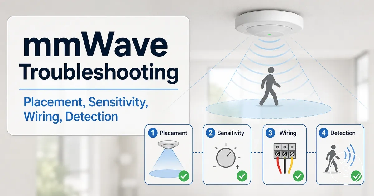
mmWave Presence Sensor Troubleshooting
When a mmWave presence sensor shows missed detection, false occupancy, unstable reporting, or failed communication, the likely cause may sit in its setup, calibration, placement, interference, power, firmware, or integration. Troubleshooting begins by classifying the symptom before choosing a safe fix or considering replacement.
Start with the observable state before changing settings or replacing the sensor. A detection problem may relate to range, sensitivity, zones, room layout, or mounting position, while a reporting problem may involve pairing, firmware, protocol, power stability, or integration. Calibration and placement changes may help only when the symptom pattern supports them, and detailed false-occupancy edge cases belong to the dedicated false-trigger context.
The appropriate check depends on the mmWave presence sensor model, room conditions, power supply, firmware, protocol, and current settings. Classifying the symptom first helps separate detection faults from reporting failures, interference, configuration mismatch, and possible replacement cues.
Common mmWave Presence Sensor Symptom Patterns
Common mmWave Presence Sensor Symptom Patterns help identify the visible symptom before selecting a diagnostic direction. Classifying the symptom pattern first makes it easier to separate missed presence, false occupancy, offline status, setup failure, calibration mismatch, interference, and possible replacement cues.
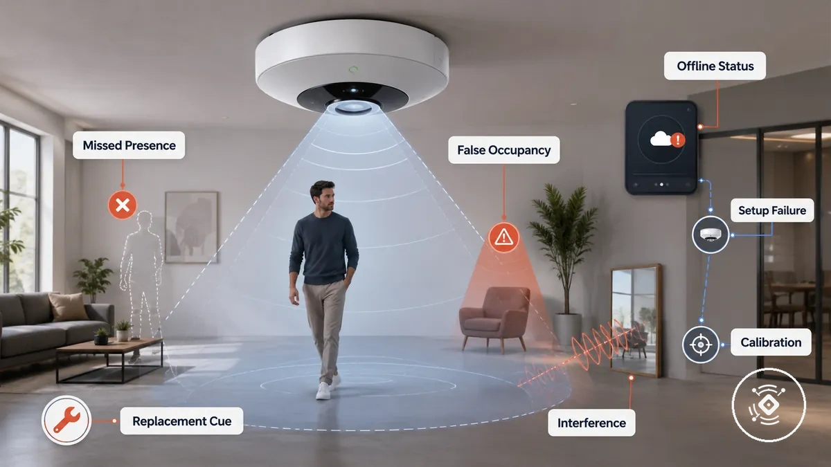
Detection state, reporting state, and room conditions often point to different first checks, even when two problems appear similar. For example, a sensor that detects occupancy but fails to report it may have a different likely cause than one that never detects presence. For broader context beyond symptom classification, see the mmWave presence sensor guide. The table below helps connect each symptom with a likely condition, an appropriate first check, and what the pattern may suggest.
| Symptom | Likely condition | First check | What it means |
|---|---|---|---|
| Missed presence | Detection range, sensitivity, or zone may not suit the environment | Review placement and detection settings | The mmWave presence sensor may not recognise occupancy consistently. |
| False occupancy | Reflection or interference may influence detection | Check nearby movement sources and room layout | The reported presence may not match actual occupancy. |
| Offline status | Pairing, reporting, or power may be interrupted | Verify connection, reporting state, and power supply | The sensor may operate locally but fail to communicate. |
| Setup failure | Configuration may be incomplete or unsuitable | Review setup and integration status | The sensor may not be ready for normal operation. |
| Calibration mismatch | Current calibration may not match room conditions | Confirm calibration after environmental changes | Detection behaviour may differ from expected results. |
| Interference | External reflections or nearby activity may affect readings | Inspect the surrounding environment for interference sources | The symptom pattern may vary as room conditions change. |
| Replacement cue | Recurring faults continue after appropriate checks | Compare persistent symptoms across different operating conditions | Replacement may be appropriate if the same fault continues under suitable conditions. |
Sensor Offline, Not Reporting, or Not Pairing
When a mmWave presence sensor is offline, not reporting, or not pairing, the reporting layer usually needs diagnosis before the detection layer. An unavailable or unpaired sensor may still detect presence locally while failing to send a state change because communication between power, pairing, firmware, protocol, or integration layers has been interrupted.
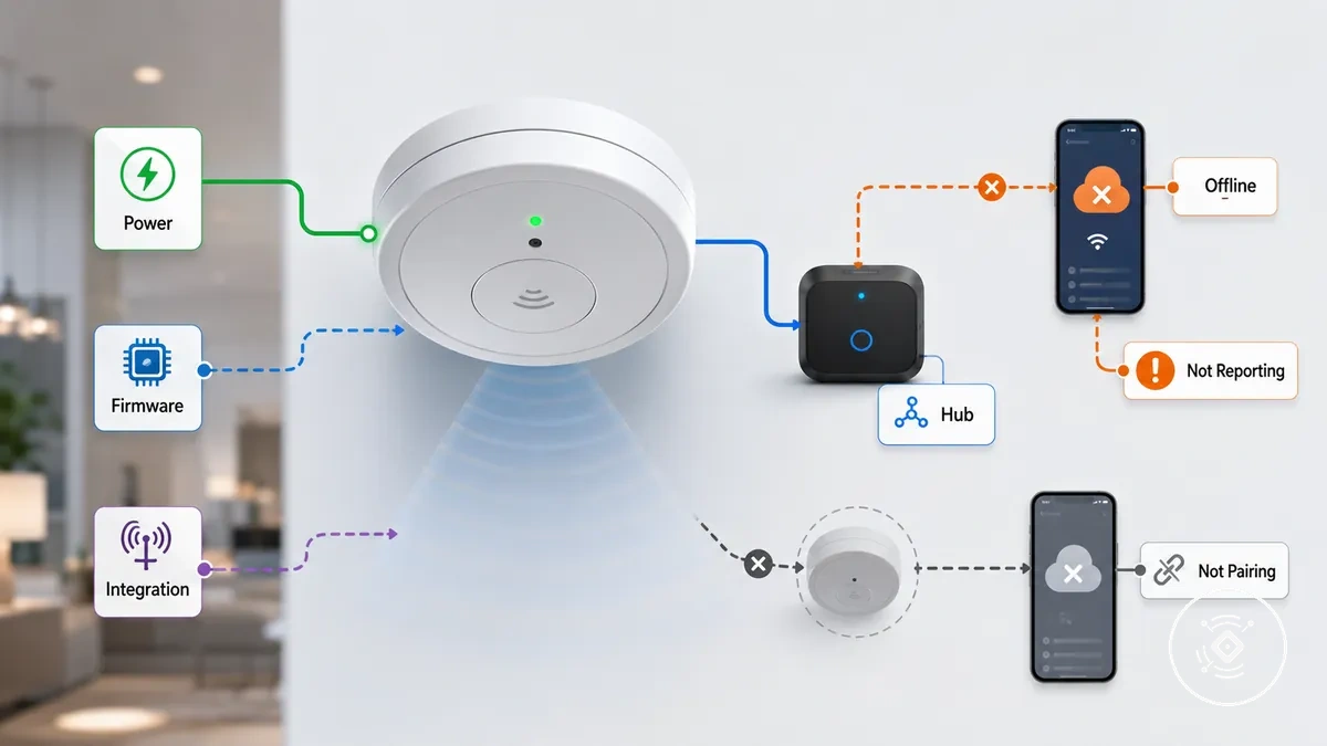
Sensor Offline, Not Reporting, or Not Pairing can result from different layers, so identifying the failure point helps avoid unnecessary troubleshooting. An offline but powered sensor may indicate a reporting failure rather than a detection problem, while a sensor that is not detecting presence requires a different diagnostic path. Check power, then confirm the app or hub recognises the sensor, followed by pairing, protocol, firmware, and integration status before considering further action.
- Power layer: Confirm the sensor has power. If power is unavailable, reporting cannot continue.
- App layer: Check whether the app shows the current entity state. A delayed or unavailable state may indicate a reporting issue.
- Hub layer: Verify that the hub still recognises the sensor. An unpaired device may no longer receive or send state changes.
- Protocol layer: Review communication settings if the sensor appears disconnected after configuration changes. This may indicate an integration interruption.
- Firmware layer: Consider firmware only when recent updates or changes coincide with the reporting problem. This may help identify the affected layer.
- Integration layer: Confirm that automation receives state changes. Missing updates may indicate a reporting failure even when local detection continues.
If the problem appears limited to pairing or configuration, retrying setup may help before moving to hardware diagnosis. For broader guidance on setup problems, use the dedicated setup resource. If the sensor remains offline, unavailable, or not reporting after software and integration checks, a hardware inspection may be the next appropriate step.
Power, Cable, and Connector Checks
Unstable power delivery can mimic a mmWave presence sensor fault by causing offline status or unstable reporting. Power, Cable, and Connector Checks focus on safe external inspection before deeper diagnosis.
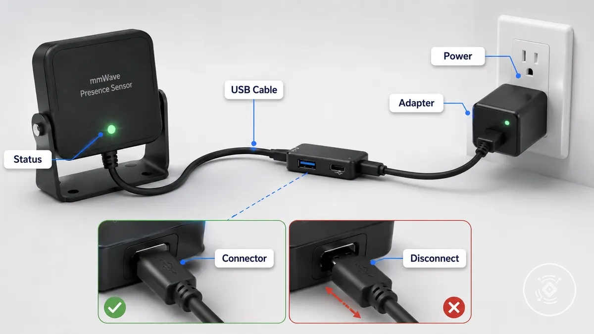
Check the external power path to determine whether an intermittent disconnect or availability issue is affecting the sensor.
- USB cable: Inspect the USB cable for visible damage, loose cable fit, or movement that repeatedly causes an intermittent disconnect.
- Adapter: Confirm the adapter provides stable power delivery. If reporting changes only with one adapter, power quality may be contributing to the symptom.
- Connector seating: Ensure the connector is fully seated. A loose connector may result in reporting dropouts or offline status.
- Hub or extension: If a USB hub or extension cable is used, check whether the availability problem appears only through that connection.
- Repeatability: Observe whether gentle cable movement consistently causes a disconnect or reporting failure. A repeatable symptom can help isolate the external power path.
If the same symptom continues after these non-invasive checks, continue with the next diagnostic stage rather than attempting rewiring, device disassembly, or other unsafe electrical work.
Firmware, App, and Integration Reporting Issues
Reporting issues can occur even when a mmWave presence sensor detects presence locally. Firmware, App, and Integration Reporting Issues focus on the software reporting layer, so confirm reporting before assuming a physical detection failure.
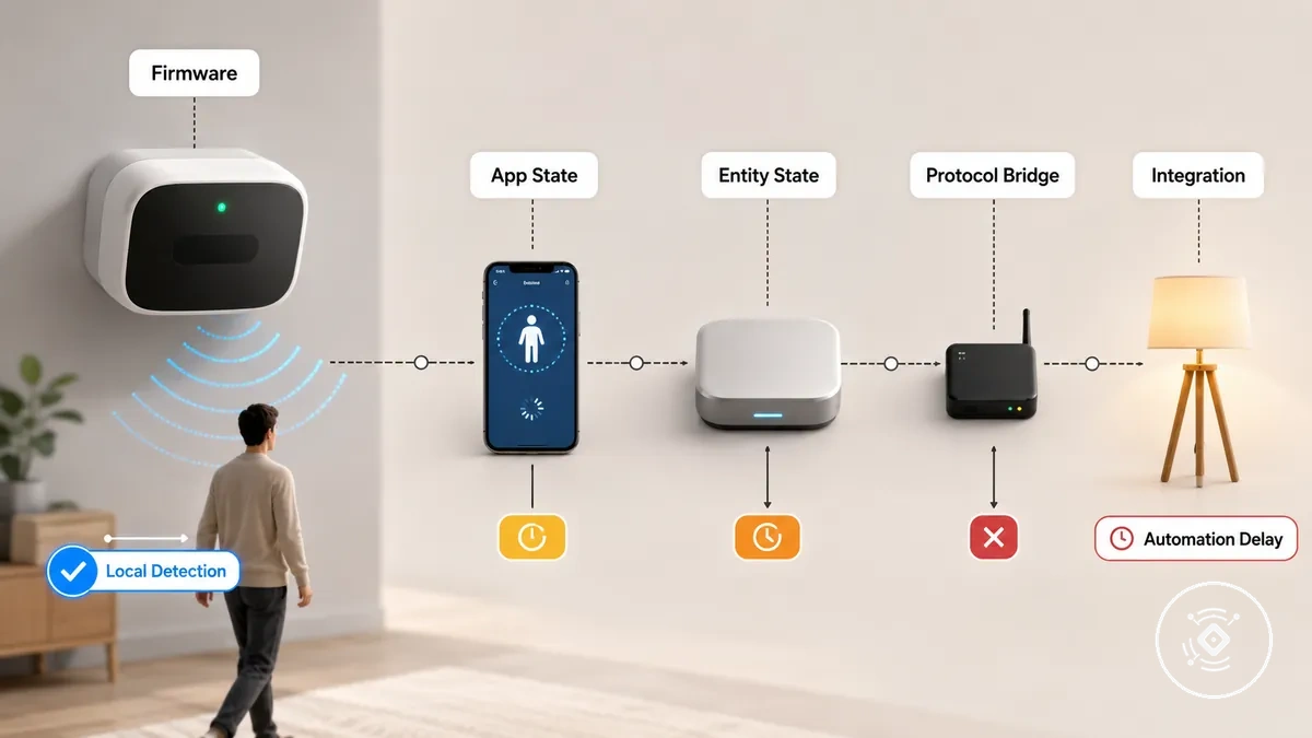
Firmware, App, and Integration Reporting Issues are reporting-layer checks rather than physical detection tests.
- Firmware: Check whether a recent firmware version change coincides with the reporting issue. If it does, the reporting outcome may be affected.
- App state: Confirm the app state reflects the current entity state. A delayed or stale entity state may indicate a reporting issue instead of a detection fault.
- Protocol bridge: Verify that the hub, protocol bridge, and integration remain synchronized so state reporting can continue.
- Automation delay: If reported changes arrive late, an automation delay or bridge synchronization issue may be affecting the reporting outcome.
- Integration: Review integration permissions or configuration if the entity state is unavailable after other software-layer checks.
A sensor can detect movement locally while failing to report its entity state through the app or hub. By contrast, complete detection failure means the sensor does not recognise presence locally, so the issue may extend beyond the software reporting layer.
Missed Presence and Movement-Only Detection
When a mmWave sensor detects movement but misses still occupancy, the sensor is not necessarily faulty. Check the detection zone, sensitivity, timeout, room geometry, mounting angle, and model capability before considering replacement, because these conditions can affect the detection outcome.
Missed Presence and Movement-Only Detection depends on how presence is represented within the monitored area rather than on a single setting. Occupant position, micro-movement, furniture obstruction, and the configured zone can influence whether presence remains detected after movement stops. Increasing sensitivity may help in some situations, but the correct adjustment depends on the symptom, room conditions, and the mmWave sensor's capability.
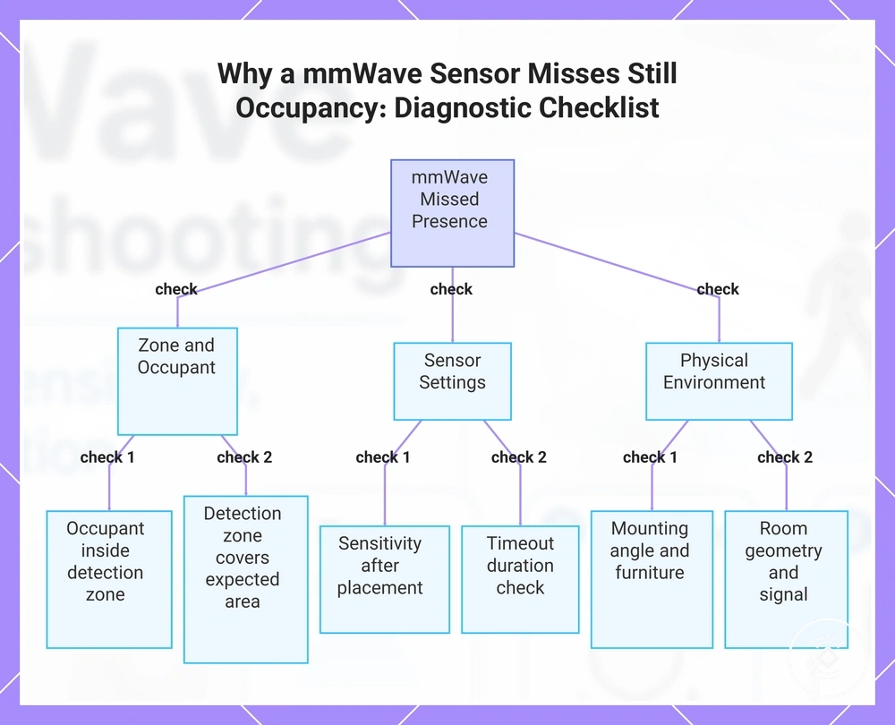
Use this checklist to verify which condition is most likely affecting the mmWave sensor before changing multiple settings:
- Occupant position: Check whether the person remains inside the intended detection zone during still occupancy.
- Detection zone: Confirm the configured zone covers the area where presence is expected.
- Sensitivity: Review the current sensitivity value only after confirming placement and room conditions. A higher value may help in some cases but is not a universal solution.
- Timeout: Check whether the timeout value clears presence before normal occupancy ends.
- Mounting angle and furniture: Verify that the mounting angle and nearby furniture are not limiting the signal path or creating a dead zone.
If a person remains motionless behind furniture, a different adjustment may be appropriate than when the person is outside the intended detection zone. Compare the room layout with detection zones and sensitivity before changing multiple settings at once.
This chart shows the key factors to check when a mmWave sensor detects movement but misses still presence, helping to identify the likely cause before considering replacement.
Still Occupancy Drops or Timeout Problems
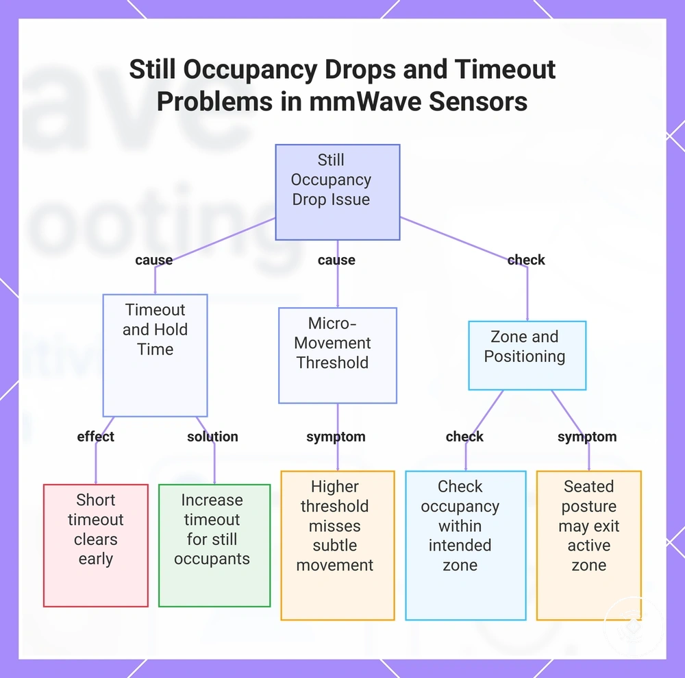
When a mmWave sensor detects a person initially but clears presence too early, the likely condition may involve timeout duration, hold time, micro-movement threshold, or zone behaviour. Check when the occupancy state changes and whether the person remains still within the intended room zone.
A short timeout or hold time may cause the sensor to clear presence before normal still occupancy ends, while a higher micro-movement threshold may miss subtle movement from a seated person. If the symptom appears only during prolonged stillness, a longer timeout or adjusted hold time may help because the sensor needs more time before clearing the state, but the suitable value depends on room use and model. If the state clears only in one seated posture, check whether that position remains inside the active zone before changing other settings.
This chart helps identify why a mmWave sensor clears presence too early and what to check, focusing on timeout settings, micro-movement threshold, and zone positioning.
Range, Zone, and Sensitivity Mismatch
When a mmWave sensor misses presence, a mismatch between range, zone, sensitivity, and room layout may imitate a sensor fault. Check whether the symptom occurs outside the intended coverage area or within an excluded or weakly detected zone.
Range, Zone, and Sensitivity Mismatch can change how the mmWave sensor responds under the same room condition. Use this table to compare each attribute with the observed symptom before changing multiple values.
| Attribute | Condition | Detection effect | First check |
|---|---|---|---|
| Range | The expected position may sit near or beyond the configured coverage limit. | Presence may be missed in the far part of the room. | Compare the missed position with the intended coverage area. |
| Zone | The occupied area may be excluded or only partly included. | The sensor may detect movement elsewhere but ignore the affected area. | Confirm that the active zone includes the location where the symptom occurs. |
| Sensitivity | The threshold may not suit the room condition or expected movement level. | Lower sensitivity may miss subtle presence, while higher sensitivity may extend detection beyond the intended area. | Adjust sensitivity only when the symptom and room layout support the change. |
| Dead spot | Furniture, room geometry, or zone boundaries may weaken coverage in one location. | Presence may drop only from a specific position. | Check whether the missed area remains consistent across repeated observations. |
False Occupancy and Short False Triggers
Persistent false occupancy and a short false trigger are different symptoms and should be checked separately. False occupancy remains active in an empty room, while a brief spike appears and clears quickly; trigger duration and repetition are the first conditions to verify.
Nearby movement, reflections, through-wall detection, sensitivity, or automation delay may produce similar occupancy results for different reasons. A repeated active state may suggest that the mmWave sensor continues receiving a signal, while a short spike may reflect brief movement or delayed state reporting. Check the empty-room state, trigger duration, repeated pattern, nearby activity, reflective surfaces, and current sensitivity value before changing settings.
Use this table to connect each symptom with a likely condition and a safe adjustment direction.
| Symptom | Condition | Likely cause | Safe adjustment |
|---|---|---|---|
| Occupancy remains active | The room is empty, but the presence state does not clear | Nearby movement, reflections, through-wall detection, or sensitivity may be contributing | Check repeated patterns and review zone or sensitivity settings only when the observed signal supports the change |
| Short false trigger | The state changes briefly and then clears | A temporary movement signal, reflection, or automation delay may be involved | Compare trigger duration with nearby activity and reported state timing |
| Repeated spikes | The same brief trigger returns under similar room conditions | A recurring movement source or reflective surface may be influencing the signal | Check whether the pattern aligns with a specific area or event before adjusting the zone |
| False state after a setting change | The symptom begins after sensitivity or zone values are modified | The new value may extend detection beyond the intended area | Compare the current value with previous room behaviour and adjust gradually |
Detailed edge cases involving false triggers and false occupancy belong to the dedicated troubleshooting context, while this section focuses on initial symptom triage.
Fans, Pets, Appliances, and Moving Room Objects
When false occupancy appears unexpectedly, ordinary room activity may be creating a detectable signal under certain conditions. Check whether movement from objects inside the detection zone matches the timing or location of the symptom before changing mmWave sensor settings.
Use this checklist to determine whether a moving object may be contributing to a false trigger or false occupancy condition.
- Fan: If airflow repeatedly moves nearby objects within the detection area, the changing movement pattern may contribute to a false occupancy outcome.
- Curtains: Curtains that move with consistent airflow may create a repeated symptom when they overlap the active detection zone.
- Pets: A pet moving through the monitored area may trigger occupancy, depending on the sensor configuration, movement pattern, and sensitivity.
- Robot vacuum: A robot vacuum travelling through the monitored zone may create a temporary false trigger if its movement overlaps the active detection area.
- Appliances: Appliances with moving parts or visible motion may contribute to unexpected occupancy reports when their movement occurs within the monitored area.
- Vibrating objects: Repeated vibration near the mmWave sensor may influence detection in some room conditions. If the symptom appears only while the object is active, check whether sensitivity reduction, zone exclusion, or placement adjustment is the most appropriate next step.
Reflections, Glass, and Through-Wall Detection
When a mmWave sensor reports occupancy in an empty room, reflected signals or detection beyond the intended space may be contributing. Check whether the symptom aligns with nearby glass, mirrors, metal surfaces, thin walls, open doorways, or movement in an adjacent room.
Glass, mirrors, and metal surfaces may redirect the signal inside the room, depending on material, distance, angle, and sensitivity. Thin walls or open doorways may allow adjacent-room movement to influence the reported state under certain conditions. Reflection keeps the signal path within the room, while through-wall or doorway detection links a false trigger to activity beyond the intended area. Compare the timing and location of the occupancy change before adjusting zone, sensitivity, or placement.
Signal Noise, Interference, and Power Stability
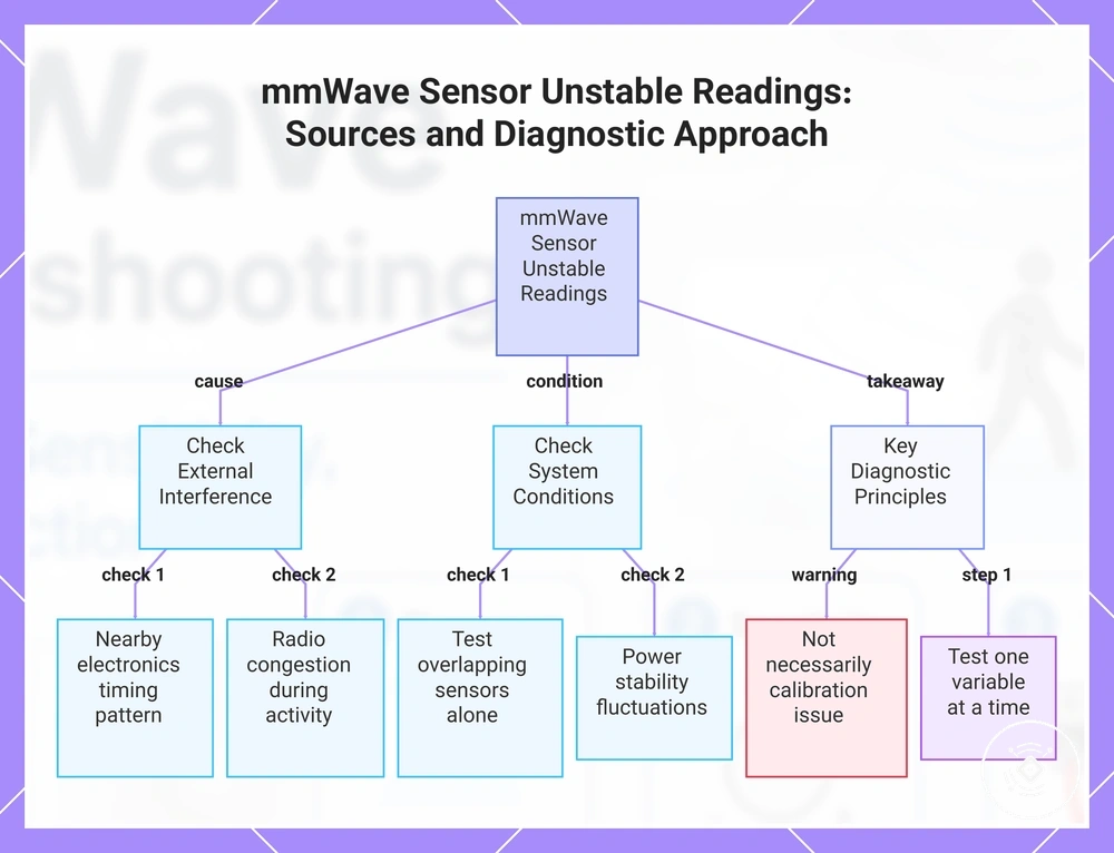
When a mmWave sensor produces unstable readings, signal noise, interference, overlapping detection fields, or power instability may be contributing. Check whether the symptom follows a repeated timing pattern or changes when one suspected source is isolated before assuming calibration is the cause.
Inconsistent behaviour does not necessarily indicate a calibration problem. Nearby electronics, radio congestion, unstable power, or another mmWave sensor may affect reporting under certain room conditions. Testing one variable at a time helps connect each symptom to a specific condition instead of treating the sensor as faulty.
Use this checklist to isolate the suspected source and verify its effect before changing multiple settings.
- Nearby electronics: Check whether unstable readings appear only while a nearby device is operating. A repeated timing pattern may indicate a local interference condition.
- Radio congestion: Observe whether reporting becomes delayed or inconsistent during periods of increased wireless activity. This may suggest a communication-related condition rather than a detection fault.
- Overlapping mmWave fields: If another mmWave sensor covers the same area, test each sensor independently. A change in the symptom may indicate overlapping detection fields.
- Power stability: Check whether the sensor resets, drops readings, or changes state during repeated power fluctuations. If the pattern follows the power source, unstable delivery may be contributing.
- Repeated timing pattern: Record whether the symptom occurs at consistent intervals or during the same room activity. A repeatable pattern can help identify the suspected source.
- One-variable testing: Change or isolate only one condition at a time so the effect of each decision is easier to evaluate.
This checklist helps identify whether signal noise, interference, overlapping detection fields, or power instability causes unstable mmWave sensor readings and emphasizes one-variable testing before assuming a calibration fault.
Strong Electromagnetic Fields and Power Supply Ripples
When a mmWave sensor shows intermittent or patterned state changes, nearby electronics or unstable power may be contributing. Check whether the symptom appears only when a specific device, power source, or lighting circuit is active.
Use this checklist to isolate each suspected source through safe, observable tests.
- Power adapter: If reporting becomes unstable only with one adapter, that power source may be contributing to the condition.
- USB cable: Check whether cable movement or pressure matches the timing of a dropout, delayed state, or detection change.
- Hub: If the sensor is powered through a hub, test whether the symptom changes when that hub is removed from the power path.
- Smart plug: Observe whether state changes coincide with the smart plug switching or restarting. A repeated pattern may justify testing another stable power path.
- Motorized appliance: If the symptom appears only while a nearby motorized appliance operates, briefly isolate that source and observe the result.
- Router proximity: Check whether increasing distance from nearby networking equipment changes the reporting or detection pattern.
- Lighting driver: If instability follows a light switching on, dimming, or turning off, test the mmWave sensor while that lighting source is inactive.
Multiple mmWave Sensors Facing the Same Area
When two or more mmWave sensors monitor the same area, overlapping sensing fields may contribute to inconsistent reporting under certain conditions. Check whether the symptom appears only where sensor position, facing direction, or a shared detection zone overlaps before assuming a sensor fault.
Use this mini-test sequence to verify whether overlapping sensing fields are contributing to the observed condition.
- Sensor position: Check whether both mmWave sensors monitor the same occupied area. A shared coverage region may contribute to the symptom.
- Facing direction: Compare the direction each sensor faces. Sensors aimed toward the same location may produce less predictable reporting in some room layouts.
- Detection cone: Observe whether the detection cones overlap where unstable reporting occurs. Focus on the affected area rather than the entire room.
- Shared zone: Check whether both sensors report activity for the same physical zone at the same time.
- Simultaneous reporting: Observe each sensor independently when practical. If the symptom changes while only one sensor reports, the overlap condition may be contributing.
Placement and Mounting Conditions That Change Detection
Placement and mounting conditions can change how a mmWave sensor handles missed detection and false occupancy. Check whether the symptom follows mounting height, orientation, angle, distance, an obstruction, or a nearby surface before changing settings.
Mount type, bracket position, furniture, and line-of-sight conditions may alter the signal path and detection outcome. A local adjustment may help when one physical condition clearly matches the symptom. If the intended area cannot be covered without repeated blind spots or unwanted detection, the mounting layout may need redesign rather than another setting change.
Use this placement-check table to compare each mounting condition with the observed symptom and the next diagnostic check.
| Placement attribute | Condition | Possible detection outcome | Diagnostic check |
|---|---|---|---|
| Mount type | The wall, ceiling, shelf, or bracket position changes the sensor's facing direction. | Presence may be detected unevenly across the intended area. | Confirm that the mount type supports the required coverage direction. |
| Height and orientation | The sensor may sit above, below, or away from the main occupancy area. | Missed detection may occur in seated or low-movement positions. | Compare the sensor orientation with the area where the symptom occurs. |
| Angle and distance | The sensor may face past the intended zone or cover more space than required. | The outcome may include a blind spot or unwanted occupancy detection. | Check whether the symptom follows the current angle and distance. |
| Furniture and obstructions | Large objects may interrupt or redirect the signal path. | Presence may drop behind furniture or remain inconsistent in one location. | Check whether the affected position is obstructed relative to the sensor. |
| Reflective surfaces | Nearby glass, mirrors, or metal surfaces may change signal behaviour. | False occupancy or unstable detection may appear near those surfaces. | Observe whether the symptom changes when the sensor angle or location changes. |
| Bracket stability | A loose or shifting bracket may alter the sensor's orientation. | Detection behaviour may change after movement or vibration. | Confirm that the mounting position remains stable during normal use. |
When these checks show that the room cannot be covered reliably from the current position, review deeper placement problems before making further setting changes.
Orientation, Height, and Room Coverage Problems
When a mmWave sensor misses part of a room or detects beyond the intended area, mounting orientation and height may be contributing. Check whether the symptom follows the sensor direction, tilt angle, room size, or occupant location, because the suitable mounting condition depends on the model and room.
Use this checklist to compare each mounting attribute with the observed coverage condition.
- Ceiling mount: A ceiling-mounted sensor may cover the room differently depending on height, direction, and model capability. Check whether missed detection occurs near room edges or in low-movement positions.
- Wall mount: A wall-mounted sensor may favour the area directly in front of it. Check whether occupancy drops occur to the side or outside the intended direction.
- Tilt angle: A tilt that points above or below the target area may create uneven detection. Adjust the angle only when the symptom matches that part of the room.
- Sensor direction: The facing direction may extend detection into an unintended area or leave part of the room weakly covered. Compare the outcome with the sensor's current aim.
- Room size: A larger or irregular room may exceed the practical coverage of the current mounting condition. Check whether the problem appears consistently in the same distant area.
- Occupant location: Seated, standing, or low-movement positions may produce different outcomes depending on orientation and height. Use the affected location to decide whether a mounting change is justified.
Objects That Block or Distort the Detection Area
When a mmWave sensor misses part of the target zone or reports an unexpected state, a nearby barrier or surface may be affecting the signal path. Check whether the symptom begins behind, beside, or near a shelf, cabinet, screen, furniture item, metal surface, glass panel, or moving décor.
Use this obstruction checklist to compare each local condition with the observed detection effect.
- Shelves and cabinets: A large unit positioned between the mmWave sensor and the target area may reduce detection behind it, depending on material, size, distance, and angle.
- Screens: A screen placed across the intended path may weaken or redirect detection in the area immediately beyond it.
- Furniture: Tall or dense furniture may create a local missed-detection condition when the occupant remains behind or close to it.
- Metal objects: A metal surface may redirect or distort the signal rather than act as a simple physical block, which can produce an unexpected outcome nearby.
- Glass: A glass panel may change signal behaviour under certain placement conditions, so check whether the symptom follows its position or angle.
- Moving décor: Hanging or rotating décor may contribute to an unstable state when its movement overlaps the monitored area.
Physical blocking usually affects the area behind a barrier, while reflective distortion may shift or extend detection around a surface. Compare the symptom location with the barrier position before changing settings.
Calibration and Setting Checks Before Hardware Changes
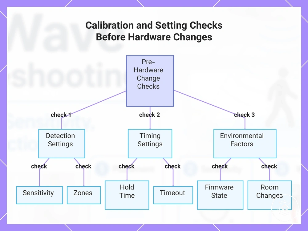
Calibration should follow symptom identification, placement checks, and basic reporting checks before hardware changes are considered. A mmWave sensor may respond differently when sensitivity, zones, hold time, timeout, threshold, firmware state, or room conditions no longer match the observed symptom.
Change one setting at a time and compare its effect with the original condition. A value change is useful only when it addresses a clear symptom, such as missed presence, early clearing, false occupancy, or inconsistent reporting. If the same outcome remains after relevant settings, room changes, and firmware state have been checked, hardware checks may become reasonable.
Use this stepwise checklist to decide whether each setting still needs adjustment or whether configuration options have been exhausted.
- Sensitivity: Check whether the current value matches the observed detection condition. Adjust it only when the symptom suggests that subtle presence is missed or unwanted activity is being detected.
- Zones: Confirm that the intended area is included and unwanted areas are excluded. A zone change may help when the symptom follows a consistent location.
- Hold time: Review whether presence clears too soon after movement reduces. A longer value may help when early clearing is the confirmed symptom.
- Timeout: Check whether the current timeout matches normal room use. Change it only when the clearing pattern supports that decision.
- Detection threshold: Compare the threshold with the movement the sensor is expected to recognise. Avoid large changes without a clear symptom-based reason.
- Firmware state: Confirm whether the reporting or detection condition began after a firmware change. If no timing link exists, firmware may not be the primary cause.
- Room changes: Check whether furniture, surfaces, occupancy patterns, or nearby activity changed after the original calibration. Recalibration may be reasonable when the room condition has changed materially.
When deeper criteria are needed for selecting values, review the dedicated calibration settings guidance. If relevant settings have been tested methodically and the same symptom remains under stable room conditions, checking the cable, bracket, sensor module, or related hardware may be appropriate.
This chart shows the key calibration settings to verify before considering hardware changes for a mmWave sensor, organized into detection, timing, and environmental checks.
Detection Zone and Threshold Adjustments
Zone and threshold changes should match a specific mmWave sensor symptom rather than increase every value. Check whether the condition involves a missed area, unwanted detection, weak near-field response, distant false activity, or early clearing before making one calibration change.
Use this table to connect each attribute with a targeted adjustment and the expected symptom change.
| Attribute | Adjusted value or condition | Expected symptom change | Decision check |
|---|---|---|---|
| Zone inclusion | Include the area where presence is repeatedly missed. | Detection may improve within that part of the room. | Confirm that the symptom consistently occurs inside the omitted zone. |
| Zone exclusion | Exclude an area linked to repeated unwanted activity. | False detection may reduce when the source remains outside the intended zone. | Check that the excluded area is not required for normal occupancy detection. |
| Near-field sensitivity | Raise or lower the value only when the symptom occurs close to the sensor. | Close-range detection may become more responsive or less prone to unwanted signals. | Match the change to a repeated near-field condition before adjusting it. |
| Far-field sensitivity | Adjust the value when missed or unwanted detection occurs farther from the sensor. | Distant presence may become more consistent, or unwanted far-area activity may reduce. | Verify that the symptom follows distance rather than placement or obstruction. |
| Threshold value | Change the threshold gradually when the sensor reacts too easily or misses subtle presence. | The mmWave sensor may become more selective or responsive under the observed condition. | Compare one threshold change with the original symptom before continuing calibration. |
| Hold time | Increase or reduce the value only when occupancy clears too early or remains active too long. | The reported state may better match the observed occupancy duration. | Check that timing, rather than zone or sensitivity, is causing the symptom. |
Recalibration After Room or Furniture Changes
When a previously stable mmWave sensor develops a new symptom after the room changes, recalibration may be needed. Check whether the detection condition changed after furniture, mirrors, fans, appliances, brackets, curtains, or the room layout were altered.
Use this mini-checklist to identify whether the changed item affects calibration or requires physical repositioning.
- Moved furniture: A new position may alter the signal path or target area, which can cause missed detection or unexpected occupancy.
- New mirrors: A mirror added near the monitored area may change signal behaviour under some placement conditions.
- Fans: A fan or nearby moving item may create a repeated symptom when its movement overlaps the sensing area.
- Appliances: A newly installed or relocated appliance may change local movement or signal conditions while operating.
- Brackets: A shifted or replaced bracket may change the mmWave sensor angle, making repositioning more appropriate than recalibration alone.
- Curtains: New or repositioned curtains may introduce movement or alter the area between the sensor and the target zone.
- Room layout: A wider layout change may require both a calibration check and a review of the sensor position.
Recalibration is more suitable when the sensor position remains appropriate but the room condition has changed. Repositioning may be needed when a bracket, target area, or physical layout no longer matches the original placement.
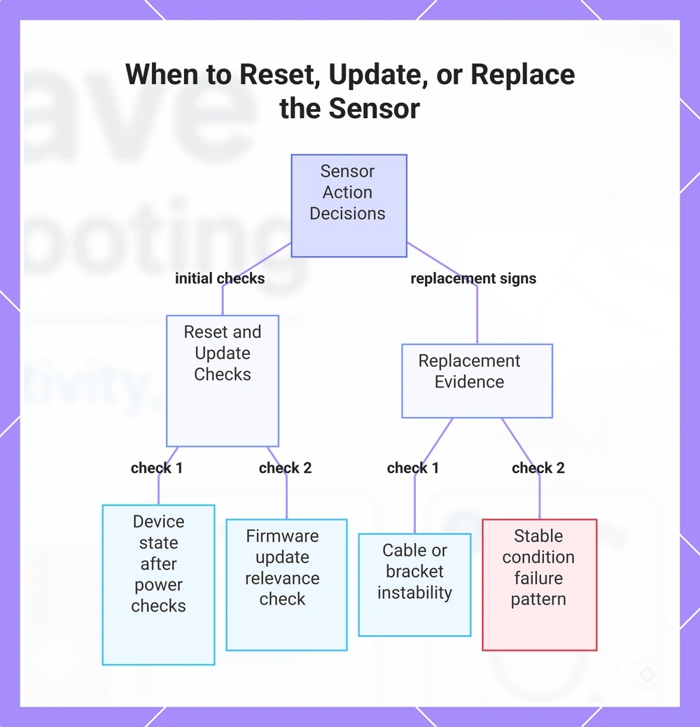
When to Reset, Update, or Replace the Sensor
Reset, firmware update, or replacement decisions should follow evidence from power, reporting, placement, interference, and calibration checks. Confirm whether the symptom points to a temporary device state, an accessory condition, or repeated mmWave sensor failure before choosing the next action.
A reset may be reasonable when configuration or reporting remains inconsistent after basic checks. A firmware update may be relevant when an available update matches the observed condition or the symptom began after a software change. Accessory replacement may be more appropriate when the fault follows a cable or bracket, while sensor replacement becomes more reasonable when the module shows the same failure under stable conditions.
Use this criteria checklist to separate reset, update, accessory replacement, and sensor replacement decisions.
- Device state: If the mmWave sensor remains unavailable or reports an abnormal state after power and connection checks, a reset may help determine whether the condition is configuration-related.
- Firmware update: Check whether an update is available and relevant to the observed symptom. Update only when the device condition or change history supports that decision.
- Reset outcome: If normal behaviour returns after a reset, continue observing the repeated pattern. If the same symptom returns under stable conditions, further checks may be needed.
- Cable condition: If the failure follows one cable and changes when that cable is isolated, accessory replacement may be more appropriate than replacing the sensor module.
- Bracket stability: If movement or a loose bracket changes the detection outcome, correct or replace the mounting accessory before treating the mmWave sensor as faulty.
- Sensor module behaviour: If reporting or detection remains unreliable with stable power, secure mounting, suitable placement, and verified settings, sensor replacement may become reasonable.
- Repeated failure pattern: A symptom that returns after reset, relevant updates, and accessory checks provides stronger evidence for replacement than a single unexplained event.
This chart outlines the key criteria for deciding whether to reset, update, replace an accessory, or replace the mmWave sensor module.