
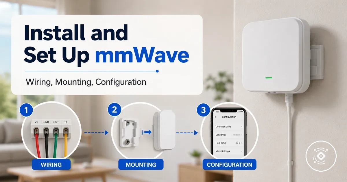
mmWave Presence Sensor Installation and Setup
Installing a mmWave presence sensor starts with confirming the power type, mounting position, wiring path, pairing method, and a post-install detection test. The setup sequence depends on the sensor type and installation conditions, so preparation, connection, pairing, and verification should follow the intended configuration.
A mmWave presence sensor installation covers the preparation, connection, mounting, smart-home readiness, and initial verification needed before calibration. For broader context, see the mmWave presence sensor hub, while this page focuses on installation and initial setup before moving into detailed preparation.
Unsafe wiring, an unsuitable mounting position, or skipped readiness checks can lead to setup issues or unreliable detection. Confirm the power type, wiring path, and device discovery before completing pairing, then perform a detection test to verify occupied state, clear state, and app status. Detailed placement, calibration, compatibility, and troubleshooting are covered in their related sections so the installation process remains clear and focused.
Installation requirements before the sensor is mounted
Installation requirements are the readiness checks that must be confirmed before mounting a mmWave presence sensor. Installation feasibility depends on the power type, mounting position, cable route, mounting hardware, and smart-home readiness.
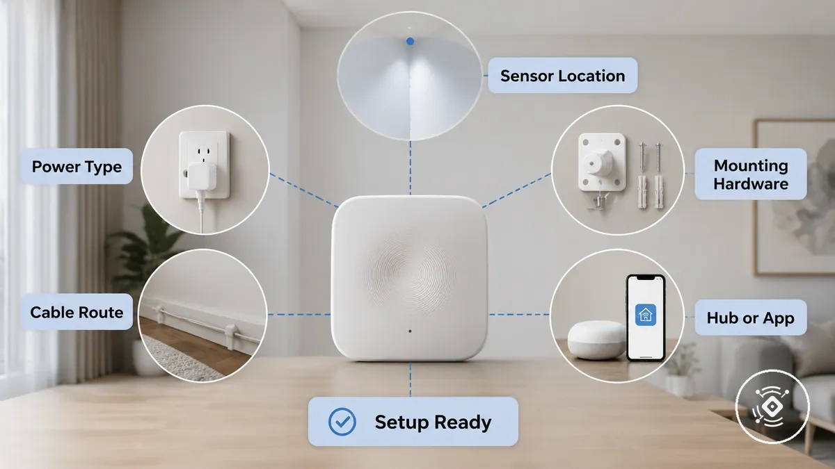
A typical room may have a suitable sensor location but no practical outlet, cable route, bracket support, hub, or app connection. Any missing condition can create a setup delay, so confirm the physical, power, and smart-home prerequisites before fixing the sensor in place.
These readiness checks can reduce later wiring, pairing, and detection problems by identifying constraints before installation begins. Deeper protocol and platform compatibility remain outside this section unless they directly affect immediate setup.
- Physical readiness: Confirm that the sensor location supports the intended wall mount or ceiling mount and that the fixing surface can accept the required bracket, screws, or other mounting hardware; an unsuitable surface may delay installation or reduce mounting stability.
- Mounting access: Check that the mounting position remains reachable for fixing, cable connection, and initial testing; restricted access can make installation and later adjustment more difficult.
- Power readiness: Verify that the required power type, adapter, outlet, or wiring path is available near the planned position; a missing or unsuitable power source can stop the setup.
- Cable readiness: Confirm that the cable route has enough reach and can follow a practical path without creating strain or obstructing the mount; a poor route may require the sensor location to change.
- Smart-home readiness: Check whether the mmWave presence sensor requires a hub, app, protocol, or network connection for pairing and device discovery; a missing requirement may prevent the sensor from joining the system.
- Setup outcome: Confirm that the physical mount, power source, cable path, and smart-home conditions can work together before mounting; any unresolved dependency should be treated as a readiness gap rather than corrected after installation.
Power type, cable route, and mounting hardware
Power type, cable route, and mounting hardware must match the sensor type and planned mounting point before installation begins. Confirm these three checks together to support stable power delivery, secure fixing, and practical cable routing.
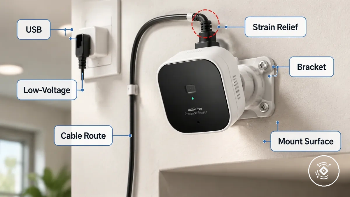
Poor cable reach or weak fixing can create an unstable setup or require the sensor to be repositioned after mounting. Exact connector, polarity, mounting hardware, and installation values depend on the device manual, so review the following checks before installation.
- Power type: Confirm whether the sensor uses USB or a low-voltage supply, and inspect the connector or terminal to help maintain stable power.
- Cable route: Check that the cable length reaches the planned mounting point without excessive tension, sharp bends, or an unsuitable cable path.
- Mounting hardware: Verify that the bracket, screws, adhesive, or flush mount method matches the fixing surface to help prevent loose mounting.
- Strain relief: Inspect the cable route near the connection point so movement or tension is less likely to affect the power connection over time.
- Device manual: Confirm any device-specific requirements for connectors, polarity, cable routing, or mounting hardware because exact values depend on the product manual.
Smart-home hub, app, and network readiness
Pairing readiness depends on the correct smart-home hub, app, protocol, and network state. When these conditions match the sensor requirements, successful discovery becomes the expected setup outcome.
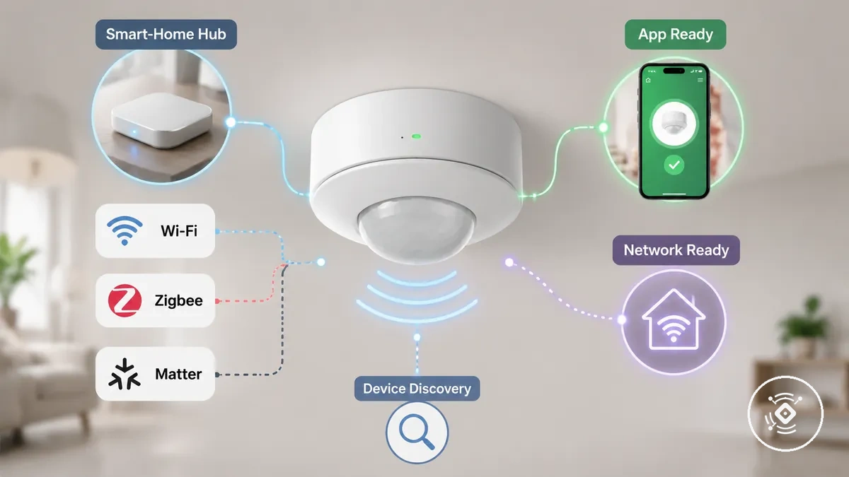
An unsupported protocol or incorrect network can prevent pairing even when the sensor is powered correctly. Review the following readiness checks before device joining. If platform support is still uncertain, see compatibility before setup for a broader compatibility review.
- Protocol readiness: Confirm that the sensor and smart-home hub support the required protocol, such as Wi-Fi, Zigbee, Matter, or another supported local integration method, before pairing.
- App readiness: Verify that the correct app is installed, the required account is available, and any necessary permissions are enabled so the sensor can enter pairing mode and discovery.
- Network readiness: Check that the intended network is available and stable because network conditions can affect device discovery and pairing.
- Hub readiness: Make sure the smart-home hub or gateway is operational and ready to accept new devices before starting the pairing process.
- Pairing outcome: Confirm that the sensor appears during discovery; if it does not, recheck the protocol, app, and network conditions before attempting device joining again.
Electrical safety and installation responsibility
Electrical safety and installation responsibility depend on whether the setup is USB-powered, low-voltage, or mains-adjacent. The power type, power supply, and building wiring context determine where a safe DIY boundary ends and where a stop point should be observed. If the installation boundary is unclear, stop before continuing.
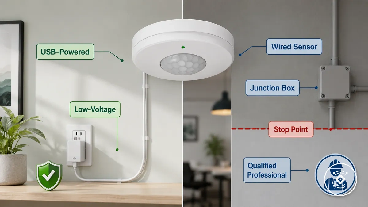
A common misconception is that every presence sensor installation is suitable for simple DIY work. USB-powered and many low-voltage setups often involve lower-risk placement, while a wired sensor installed near mains-connected wiring, a junction box, or an existing circuit may require a qualified professional. This distinction separates lower-risk installation from work with greater electrical responsibility.
If the power supply, wiring route, or existing circuit cannot be identified confidently, pause before pairing or completing the installation. Compare your installation approach with wired or wireless setup, then review the checklist below to confirm the appropriate safety boundary.
| Low-voltage or USB-powered setup | Wired or mains-adjacent setup |
|---|---|
| Usually limited to plug-in placement, adapter connection, cable routing, and mounting while following the device manual. | May involve a junction box, existing circuit, terminals, or concealed wiring where installation responsibility can extend beyond routine setup. |
| Stop if the power supply, cable route, or installation conditions are unclear. | Stop if wiring, isolation, or connection details are uncertain and consider a qualified professional. |
Caution: Electrical safety and installation responsibility depend on the power type and wiring context. Do not continue when the safe boundary cannot be confirmed.
Use the following safety checklist before completing installation:
- Power type: Confirm whether the sensor is USB-powered, low-voltage, or mains-connected before installation.
- Power supply: Verify that the intended power supply matches the device manual.
- Junction box and existing circuit: Pause if installation requires work around a junction box or existing circuit that is not clearly understood.
- Cable concealment: Check that concealed or exposed cables do not create unnecessary strain or an unsafe routing condition.
- Stop point: If installation responsibility or wiring conditions remain uncertain, stop and consult a qualified professional before proceeding.
Low-voltage USB setup conditions
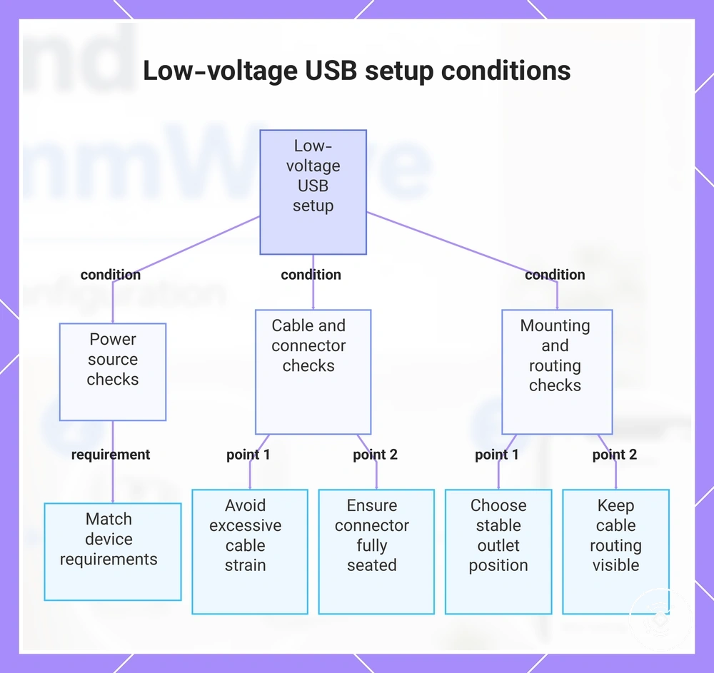
A USB-powered sensor can usually be treated as a lower-risk setup when the adapter, cable, and mounting point are suitable for the intended installation. Check the adapter output, cable support, and connector stability before use, because an unsuitable power supply, cable strain, or poor mounting conditions can reduce setup stability.
Cable strain, an unsuitable outlet position, or a loose connector can interrupt power even when the USB setup appears complete. Review the following visible conditions before mounting the USB-powered sensor.
- Adapter output: Confirm that the adapter output matches the device requirements in the product manual, because an unsuitable power adapter may affect stable operation.
- Cable support: Check that the cable reaches the mounting point without excessive cable strain, which can reduce connector stability over time.
- Connector stability: Verify that the USB connector is fully seated and remains secure during normal use to help maintain a stable power connection.
- Outlet position: Choose an outlet position that supports visible cable routing without placing unnecessary tension on the cable or connector.
- Visible cable routing: Keep the cable route visible where practical, and do not assume concealed cable routing is suitable for every installation.
This chart shows the main conditions to verify for a stable low-voltage USB sensor setup, covering power source, cable and connector, and mounting and routing checks.
Wired or mains-connected setup conditions
A wired sensor or mains-connected setup requires checks against the device manual and may require a qualified professional, depending on the power path and installation context. If the terminal type, supply voltage, or wiring responsibility is unclear, treat that uncertainty as a stop point.
Uncertainty around the terminal, power supply, junction enclosure, isolation, or strain relief should pause installation because an incorrect assumption can increase setup risk. Use the following stop-go checklist before proceeding.
- If the terminal type matches the device manual and is clearly identified: proceed only with the permitted setup checks; if the terminal purpose is unclear, stop.
- If the supply voltage matches the documented device requirement: proceed to the next readiness check; if the supply cannot be confirmed, stop.
- If the junction enclosure is suitable and accessible for the intended installation: proceed with responsibility clearly assigned; if the enclosure condition is uncertain, stop and consider professional installation.
- If isolation requirements can be confirmed for the installation context: proceed only within the documented safety boundary; if isolation cannot be verified, stop.
- If strain relief and cable support are secure: proceed with the remaining setup checks; if cable tension or movement could affect the connection, stop and correct the condition before continuing.
Preparing the mounting position for stable detection
Preparing the mounting position should balance stable detection with safe cable access before the sensor is fixed in place. A ceiling position or wall position should suit the intended line of sight, room activity, and fixing surface. Check the mounting height, angle, and nearby obstruction together before final fixing.
In some rooms, the easiest cable route leads to a mounting point near furniture or moving objects that may reduce detection stability. A less convenient cable path can provide a clearer line of sight and reduce false detection risk. Review placement before installation when the detection position and cable access cannot be balanced easily.
Choose the mounting position by comparing detection quality with cable practicality before securing the sensor. The criteria below help evaluate common mounting conditions without replacing a dedicated placement or calibration guide.
| Mounting condition | Detection quality | Cable practicality | Possible effect |
|---|---|---|---|
| Ceiling position with a clear line of sight | May support stable detection when the angle and room activity are suitable | Cable access may require a planned route and suitable fixing surface | Restricted cable access can complicate installation even when the detection position is appropriate |
| Wall position facing the occupied area | May provide reliable detection when obstructions do not block the sensing area | A nearby power route can simplify cable access | An easy cable route may still be unsuitable if the angle reduces detection quality |
| Position near moving objects | Movement from curtains, fans, or similar room activity may increase false detection risk | The location may appear convenient for installation | Detection stability should take priority over cable convenience |
| Position with limited cable access | The location may offer a clearer detection path | Cable reach and fixing access may be restricted | A different mounting position may be needed if cable access cannot be achieved safely |
Ceiling-mount installation preparation
A ceiling mount requires adequate support, cable access, and a model-appropriate orientation before a ceiling-mounted presence sensor is fixed in place. Mounting height, orientation, and the fixing method should suit the device manual and room conditions, so review the ceiling-specific checks below.
An unsupported fixing surface or poor cable entry can make installation more difficult because the sensor may not remain securely mounted or the cable route may become difficult to manage. Confirm the mounting conditions before final fixing, as bracket, flush cutout, and orientation requirements depend on the device manual.
- Mounting height and orientation: Select a ceiling position where the mounting height and sensor orientation suit the room layout and intended detection area, following the device guidance.
- Fixing surface: Verify that the fixing surface can support the ceiling mount and the selected bracket or flush cutout; unsuitable ceiling material may require a different mounting approach.
- Bracket or flush cutout: Confirm that the chosen mounting method matches the ceiling construction and the ceiling-mounted presence sensor before creating the final fixing point.
- Cable entry: Check that the cable entry and cable route provide adequate access without unnecessary strain, because restricted access can increase installation difficulty and complicate later maintenance.
- Final preparation: Confirm that the ceiling-mounted presence sensor has suitable support, orientation, and cable access before completing the installation.
Wall-mount installation preparation
A wall mount depends on the correct angle, minimal obstruction, and suitable power access before a wall-mounted sensor is fixed in place. Mounting height, wall position, cable visibility, and the selected mounting point should suit the device manual and room conditions, so review the local checks below.
A wall position affected by furniture or limited cable visibility can make installation more difficult because the line of sight may become partially obstructed. Confirm each wall-specific condition before fixing the wall-mounted sensor, as the most suitable mounting point depends on room layout and device guidance.
- Mounting height and angle: Choose a wall position where the mounting height and angle suit the intended detection area, following the device manual and room conditions.
- Corner location or flat wall: Compare a corner location with a flat wall and select the option that provides a clearer line of sight with fewer obstructions.
- Obstruction: Check whether furniture or other objects may block the wall-mounted sensor, because restricted visibility can lead to limited detection.
- Power access and cable visibility: Verify that power access and cable visibility support the planned mounting point without unnecessary cable strain or installation difficulty.
- Final preparation: Confirm that the wall-mounted sensor has suitable angle, power access, and a clear mounting position before completing the installation.
Connecting power and wiring the mmWave sensor
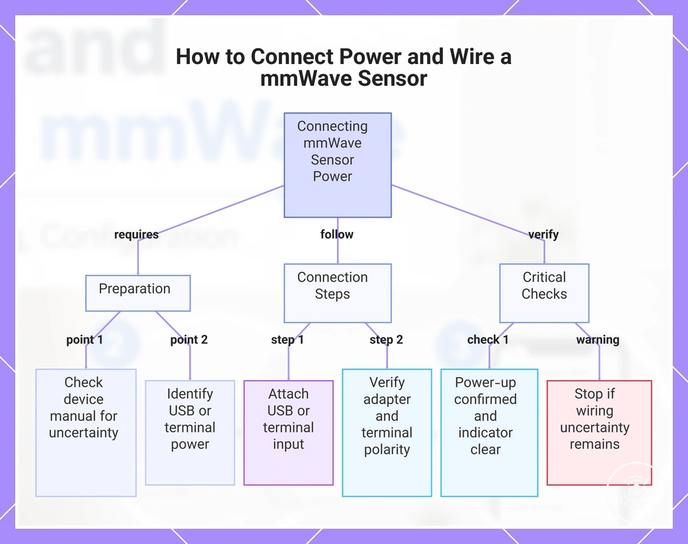
Connecting power depends on whether the mmWave sensor uses a USB-powered connection, a low-voltage input, or a wired installation. Complete the connection in the correct sequence, verify each step before power-up, and follow the device manual whenever polarity, labeled pins, terminals, or relay connections vary by model. Always check the manual before connecting the sensor if the power path is uncertain.
Power should remain stable before pairing begins because an incomplete power connection can interrupt startup or prevent pairing readiness. Follow the non-mains connection sequence below before continuing.
- Connect the USB port or power input: Attach the USB cable or approved power connection, then confirm that the connector is fully seated before continuing.
- Verify the adapter: Check that the adapter matches the device requirements so the sensor can receive stable power during power-up.
- Confirm the terminal or low-voltage input: If the sensor uses a terminal or low-voltage input instead of USB, verify the labeled pins and polarity against the device manual before applying power. Stop if the connection cannot be confirmed.
- Check the power-up result: Confirm that the sensor powers up before attempting pairing. If the power indicator or startup behavior is unclear, stop and recheck the connection path.
Caution: Do not assume that every terminal or relay connection follows the same wiring layout. Pin assignments, polarity, relay behavior, and labeled pins may vary by device model, so avoid proceeding when wiring uncertainty remains.
Terminals and relays do not mean every installation follows the same wiring method. If the power path, terminal function, or wiring responsibility cannot be confirmed from the device manual, stop before pairing begins.
This chart shows the required preparation, connection steps, and critical checks for safely powering a mmWave sensor before pairing.
USB-powered sensor connection
A USB-powered sensor should have stable power before pairing begins. Verify the adapter, cable, connector seating, and visible power status before continuing, then follow the steps below to confirm the connection.
- Connect the adapter: Attach the adapter intended for the USB-powered sensor and confirm that the power cable is securely connected.
- Check connector seating: Verify that the USB connector is fully seated because a loose connector can result in an unstable connection.
- Inspect cable strain: Confirm that the cable reaches the mounting point without unnecessary cable strain, as excessive tension may affect stable power.
- Verify the power indicator: Check whether the first power indicator shows the expected startup state described in the device manual, because indicator behavior may vary by model.
- Confirm readiness: Continue only when the USB-powered sensor has stable power and no visible connection issues before starting pairing.
If the USB-powered sensor loses power or restarts unexpectedly, recheck the adapter, cable, and connector seating before continuing. A weak power connection or excessive cable strain may indicate an unstable connection that should be corrected before pairing.
Terminal, relay, or low-voltage wiring checks
Terminal, relay, and low-voltage wiring checks must follow the device manual, and power should be isolated where the manual requires it before verification begins. If labeled terminals, polarity, or the intended connection cannot be confirmed, stop before proceeding.
Supply rating, polarity, and enclosure checks help verify that the intended connection matches the device requirements and installation context. Because relay role, load, and low-voltage wiring can vary by model, use the checklist below to confirm each condition before continuing.
- Labeled terminals: Verify that the labeled terminals match the device manual. If the terminal function cannot be identified, stop before making a connection.
- Supply rating and polarity: Confirm that the supply rating and polarity match the documented requirements. If either cannot be verified, do not proceed.
- Relay role and load: Check whether the relay role or relay output applies to the specific device and installation. Do not assume every smart-home setup requires the same relay wiring.
- Enclosure: Verify that the enclosure is suitable for the intended installation and that the connection points remain protected. If the enclosure condition is uncertain, seek device-specific or professional guidance.
- Strain relief: Confirm that strain relief supports the low-voltage wiring without unnecessary cable tension. If cable movement could affect the connection, correct the condition before continuing.
Pairing the sensor with the smart-home system
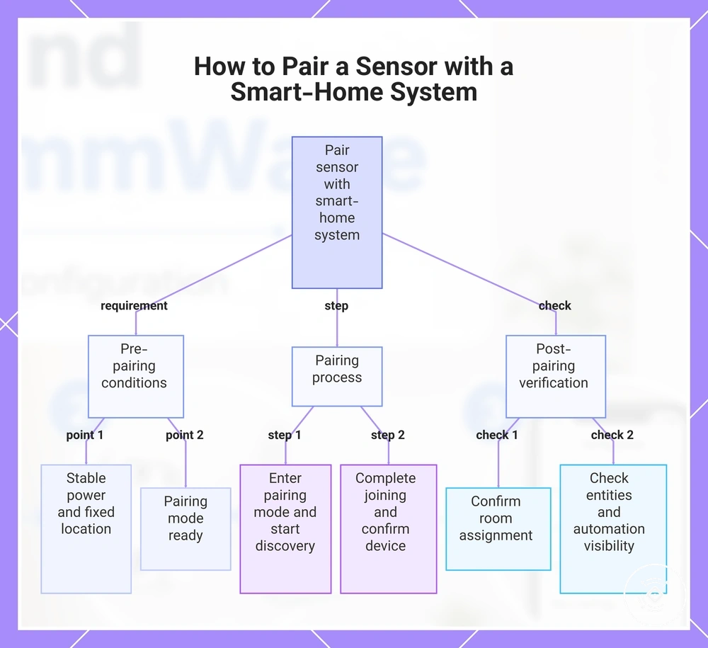
Pairing should begin only after the installed sensor has stable power and a fixed mounting location. Confirm that the sensor is ready for pairing mode before starting app discovery through the smart-home system or hub.
Protocol mismatch, hub distance, network conditions, or app state can affect app discovery even when the sensor is powered correctly. If the sensor is not discovered, verify these conditions before attempting pairing again.
- Enter pairing mode: Put the installed sensor into pairing mode according to the device manual, then confirm that it is ready for device discovery.
- Start app discovery: Open the smart-home system app or hub and begin app discovery. If the sensor does not appear, confirm that the selected protocol is supported by both devices.
- Complete device joining: Select the discovered sensor and complete pairing. Continue only after the joined device appears in the smart-home system.
- Confirm room assignment: Assign the sensor to the intended room or location so it can be identified more easily within the smart-home platform.
- Check exposed entities: Verify that the expected exposed entities are available after pairing. If only part of the expected device information appears, allow the smart-home system time to finish updating before checking again.
- Verify automation visibility: Confirm that the paired sensor is available for automation visibility. If it is not, review the pairing outcome, protocol, hub, and app state before trying again.
If the sensor appears online but exposes incomplete entities, the available sensor information may depend on the protocol, hub, app state, or platform. Confirm the device status before continuing, and leave automation design until the expected exposed entities become available.
This chart shows the step-by-step process for pairing a sensor, including prerequisites, main pairing steps, and post-pairing verification checks.
Device discovery and network joining
Device discovery requires the sensor to be in pairing mode, within a suitable hub distance, and confirmed in the app after network joining. Check pairing mode, network conditions, and join confirmation through the steps below.
- Enter pairing mode: Place the sensor into pairing mode according to the device manual, then confirm that the app or hub shows the sensor as discoverable.
- Check hub distance: Keep the sensor within a suitable hub distance during device discovery. If discovery fails, repositioning may help when signal strength is limiting the join result.
- Verify the network condition: Confirm that the required network band or mesh strength is available for the sensor protocol. If the network state is unsuitable, network joining may fail.
- Start app discovery: Begin device discovery in the smart-home system and wait for the sensor to appear. If it does not appear, confirm power, pairing mode, and protocol before retrying.
- Confirm the join result: Complete network joining only after the app provides join confirmation and the sensor appears as a joined device.
If failed discovery continues, reset or retry the pairing process only as described in the device manual. Recheck pairing mode, hub distance, network band, mesh strength, and power before attempting another network join.
Room assignment and automation visibility
Setup is not complete until the paired sensor has the correct room assignment and is visible to automations. Confirm the room assignment, occupancy entity, presence entity, and availability status before relying on the installed sensor in an automation selector.
If the sensor is assigned to the wrong room or an exposed entity remains hidden, the device can be difficult to identify or select in automations. Check the following visibility conditions before making further automation changes.
- Room assignment: Verify that the installed sensor is assigned to the intended room. If room mapping is incorrect, update it before using the sensor in automations.
- Occupancy and presence entities: Confirm that the occupancy entity and presence entity appear after pairing. Entity names may vary by platform or integration.
- Availability status: Check that the sensor reports an available device state. If the availability status shows the device as unavailable, confirm the connection before relying on automation visibility.
- Automation selector: Open the automation selector and verify that the sensor appears as a usable device. If the sensor remains hidden, review the room assignment and exposed entity availability.
Initial detection test after setup
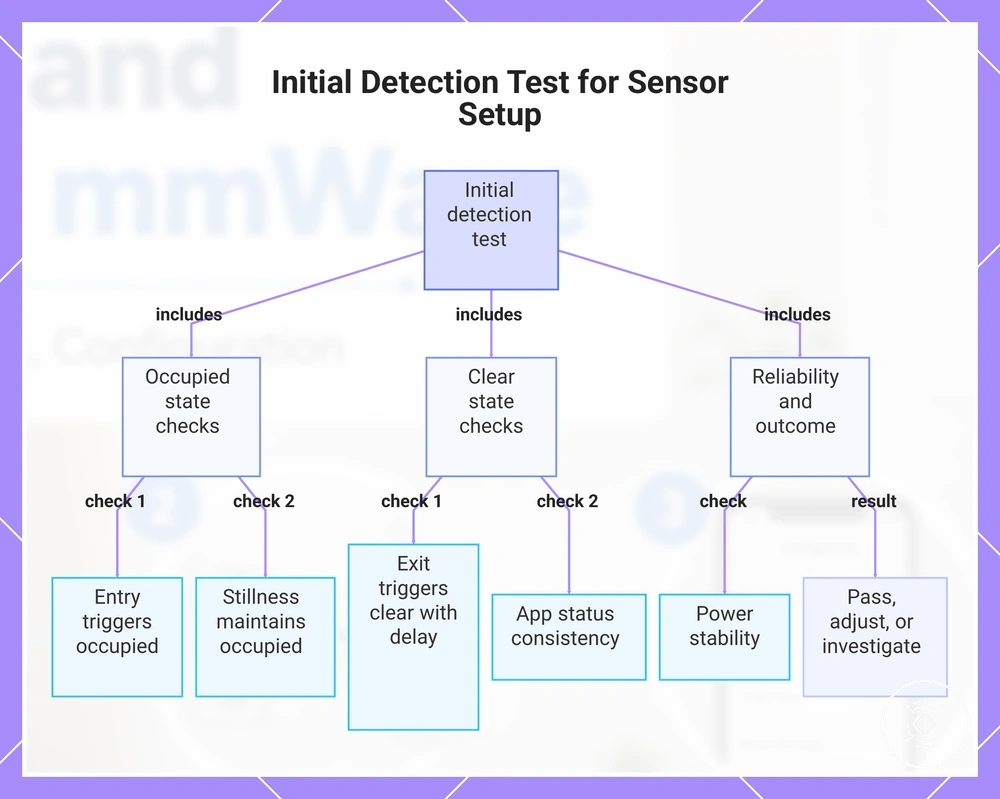
The initial detection test confirms that the installation and pairing provide a working starting point before deeper calibration. It verifies basic operation rather than perfect calibration by checking the occupied state, clear state, and app status.
Enter the room, remain still briefly, then leave the detection area while observing the reported sensor state. Use the checklist below to compare the physical movement with the reported detection result.
- Entry response: Verify that entering the room changes the sensor to an occupied state. If no change appears, adjust the test position or review the current settings.
- Stillness response: Remain still and confirm that the occupied state continues. If the sensor changes to a clear state unexpectedly, placement or settings may need adjustment.
- Exit response: Leave the detection area and observe the response delay before the sensor reports a clear state, allowing for differences in model, settings, and room conditions.
- App status: Check that the app status follows the occupied state and clear state consistently. Repeated differences between the room condition and reported state should be investigated.
- Power stability: Confirm that the sensor remains powered without repeated dropouts or restarts, because unstable power can affect the test result.
- Next action: Record the outcome as pass when the reported states remain consistent, adjust when placement or settings appear responsible, or investigate when wiring, power stability, or app reporting remain inconsistent.
Response delay, unstable power, or inconsistent app status can make a working sensor appear unreliable. Repeat the same detection check after correcting the visible condition, because comparing one controlled change at a time can simplify interpretation.
Use the decision signals from the checklist to determine the next step. Continue to calibration after a pass, adjust placement or settings when the test result changes with room conditions, or investigate wiring and power stability when inconsistent reporting continues.
The first test provides practical verification of the setup before more detailed calibration begins. Once the occupied state, clear state, and app status remain consistent, continue with the next stage of setup using the result as a verified baseline.
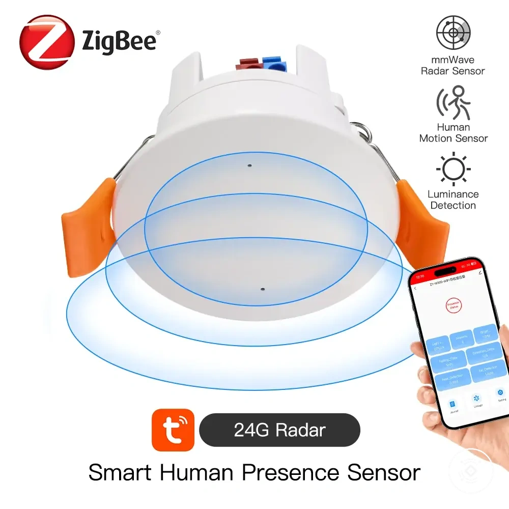
Here are product examples that may make comparison easier. Before buying, always review the compatibility criteria, essential features, and product details.
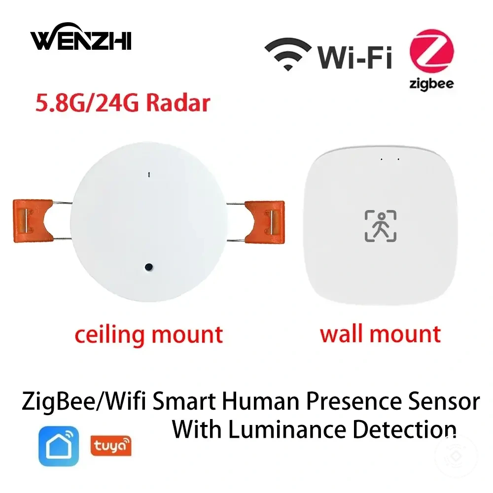
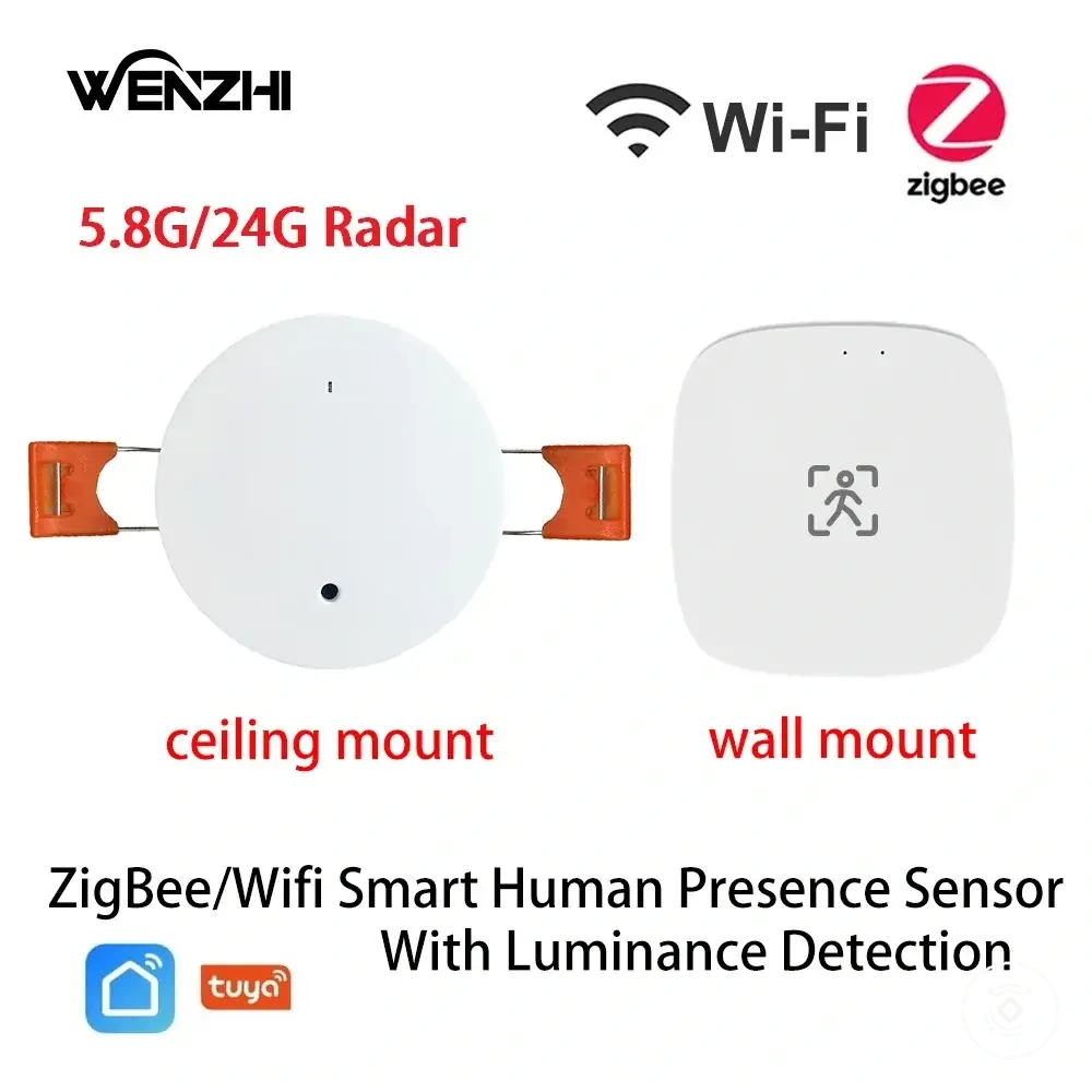
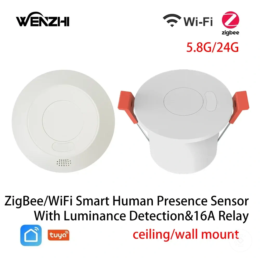
This chart shows the main checks and decision steps for the initial detection test, which verifies basic sensor operation before calibration.
Presence response and clear-state test
The presence response and clear-state test compares occupied and unoccupied room states without assuming an exact response time. Because the delay setting, model, and room conditions can affect timing, use the steps below to verify the expected response.
Stillness and room vacancy can influence how the sensor changes between states. Repeat the same local test under similar conditions when the result is unclear.
- Occupied state: Enter the room and confirm that the app reports an occupied state. If the app remains clear, the result may indicate a setup concern.
- Stillness check: Remain within the detection area and verify that the app continues to report the occupied state. An unexpected clear state may indicate that the current setup needs review.
- Room vacancy: Leave the room completely and observe whether the app reports a clear state after the configured delay setting. The response time may vary by model, settings, and room conditions.
- Expected response: Compare the reported occupied state and clear state with the actual room condition. If the reported state does not match the presence response or room vacancy after repeated checks, treat the result as a setup concern.
Signal stability and app status checks
Signal stability means the sensor stays online and reports status consistently after the initial setup. Confirm app status, signal strength, and power stability with the checklist below.
Repeated dropouts should be treated as a stability issue rather than a calibration issue. Verify the checks below first, then continue to calibration and settings only after the sensor remains consistently available.
- Online status: Confirm that the sensor remains online without repeated disconnects. Frequent changes between online and offline status may indicate repeated dropouts.
- Signal strength: Verify that signal strength and the network connection remain consistent at the installation location. If connection quality changes noticeably, review hub distance or placement before continuing.
- Power indicator: Check that the power indicator remains stable without unexpected restarts or power loss. If the indicator changes unexpectedly, inspect the adapter or wiring as appropriate for the installation.
- Event history: Review the event history to confirm that status updates follow normal room activity. Repeated gaps or unexpected events may indicate a condition that requires investigation.
- Entity availability: Verify that entity availability remains consistent in the app. If entities repeatedly disappear or become unavailable, confirm connection stability before proceeding.
Common setup mistakes that affect detection
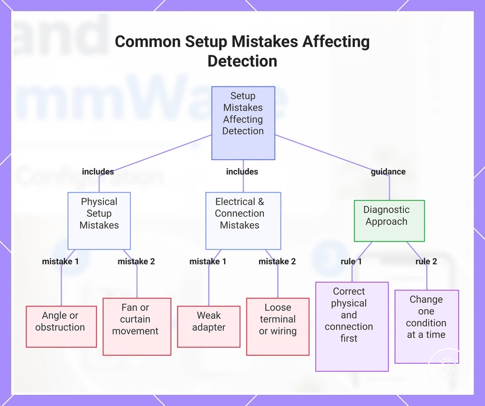
Most setup-related detection problems come from the sensor’s physical position, moving objects, power connection, wiring, or pairing stability. These conditions may contribute to false detection, missed presence, or an unstable setup, depending on the model and room environment.
Physical mistakes include an unsuitable angle, obstruction, fan or curtain movement, and nearby reflective surfaces. Electrical and connection mistakes include a weak adapter, loose terminal, or unstable network, so use the diagnostic checklist below to identify the first correction.
- Angle or obstruction: A poorly directed sensor or blocked line of sight may contribute to missed presence. Recheck the mounting angle and remove nearby obstructions before changing detection settings.
- Fan or curtain movement: Repeated movement near the sensor may contribute to false detection. Temporarily stop or isolate the moving object to see whether the symptom changes.
- Reflective object: A nearby reflective surface may affect detection differently by model and room condition. Reposition the sensor or object when the symptom appears linked to that surface.
- Weak adapter: An unsuitable or unstable adapter may cause restarts, dropouts, or inconsistent reporting. Confirm that the adapter matches the device manual and that power remains stable.
- Loose terminal or wiring: An uncertain terminal connection may interrupt power or status reporting. Stop and verify the labeled connection against the device manual before proceeding.
- Unstable network or pairing: Repeated offline states or missing updates may indicate unstable pairing or network conditions. Confirm hub, app, and network availability before repeating setup.
False detection near a moving curtain may continue even when pairing and power are stable, while missed presence behind furniture may point to angle or obstruction. Correct physical and connection conditions first, then consider calibration only if the symptom remains.
If the first correction does not resolve the symptom, use setup troubleshooting to continue with a broader diagnostic process. Avoid changing several conditions at once because doing so can make the original cause harder to identify.
Start with the condition most closely linked to the symptom, verify the result, and move to the next check only when needed. Calibration may be appropriate after placement, power, wiring, and pairing stability have been confirmed.
Here are product examples that may make comparison easier. Before buying, always review the compatibility criteria, essential features, and product details.
This chart categorizes common setup mistakes that cause false detection or missed presence, and provides diagnostic guidance for correction.
Obstructed angle, moving objects, and reflective surfaces
An obstructed angle, moving objects, and reflective surfaces can distort detection by limiting the line of sight or adding activity within the sensor view. Depending on the room condition and sensor model, the result may appear as false occupancy or missed detection.
A sensor facing a curtain moved by a fan may remain occupied when the room is empty, while furniture blocking the same view may cause missed presence. Use the checks below to identify the likely physical source and make the first local adjustment.
- Obstructed angle: A blocked or poorly directed angle may reduce the line of sight and contribute to missed detection. Check whether furniture or room features obstruct the sensor view, then adjust the angle if needed.
- Fan movement: A fan within the sensor view may act as a moving source and contribute to false occupancy in certain conditions. Stop the fan temporarily and compare the reported state.
- Curtain movement: A curtain moving near the detection area may create room activity that affects the sensor state. Secure the curtain temporarily or redirect the sensor view to see whether the symptom changes.
- Robot vacuum: A robot vacuum moving through the monitored area may be interpreted as occupancy while active. Compare the sensor state when the robot vacuum is stationary and moving to confirm whether it is the local source.
- Reflective surfaces: A reflective surface may affect detection differently according to its position, material, and the sensor model. Change the sensor angle or move the reflective object slightly to see whether the detection risk decreases.
Weak power, loose wiring, and unstable pairing
Weak power, loose wiring, and unstable pairing can cause dropout, delayed status, or failed discovery before the sensor should be considered faulty. Check the adapter rating, cable seating, terminal tightness, hub distance, and network join status first.
Basic setup checks should come before assuming device failure because intermittent behaviour may result from unstable power, a loose connection, or pairing instability. If wiring is unclear or involves a mains-connected installation, stop and seek device-specific or professional guidance before continuing.
Use the checklist below to connect each setup condition with the observed symptom and a safe first check.
- Adapter rating: An unsuitable adapter rating may contribute to unstable power or dropout. Confirm that the adapter matches the device requirements and check whether the power indicator remains stable.
- Cable seating: A partially seated cable may interrupt power or cause delayed status updates. Verify that each connector is fully seated before repeating the test.
- Terminal tightness: Loose wiring at a terminal may contribute to intermittent operation. Check only the visible condition permitted by the device manual, and stop if the wiring is unclear or mains-connected.
- Hub distance: Excessive hub distance may contribute to unstable pairing or failed discovery. Temporarily reduce the distance to see whether the connection becomes more consistent.
- Network join status: An incomplete network join may leave the sensor offline or delay status reporting. Confirm that the sensor remains joined before attempting pairing again.