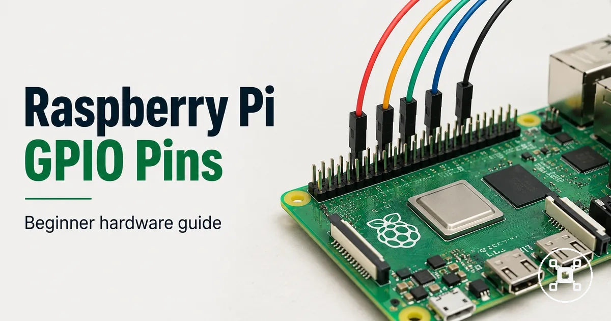
Raspberry Pi GPIO pins explained for beginners
Raspberry Pi GPIO pins are the hardware interface that lets a Raspberry Pi connect with electronics by reading input signals, sending output signals, and controlling connected components. The GPIO header provides physical connections for beginner electronics projects that use signal paths between the board and external components. GPIO pins are designed for hardware interaction through defined pin roles, and they require attention to the pinout, voltage, current, and safety requirements of the connected component.
The GPIO header provides physical connections for beginner electronics projects that use signal paths between the board and external components.
When a Raspberry Pi is used with jumper wires, a breadboard, sensors, or simple components, GPIO connections create a way to build and test electronic circuits while learning how inputs, outputs, and signals work. Beginners need to identify the correct GPIO header connection before wiring because the board model, component type, voltage requirements, and current needs affect how the connection should be made. The Raspberry Pi hub provides the broader Raspberry Pi context for choosing, setting up, and using the board with different hardware connections.
A GPIO header includes different pin roles, including signal connections alongside power and ground connections.
Raspberry Pi GPIO pins provide a connection system for learning electronics, but they are separate from standard ports such as USB, HDMI, Ethernet, and wireless connections. A GPIO header includes different pin roles, including signal connections alongside power and ground connections. Safe wiring requires checking the relevant pinout and matching the GPIO connection method to the board model and the connected electronic component.
Table of Contents
What Raspberry Pi GPIO pins are
Raspberry Pi GPIO pins are general-purpose input/output connections on the Raspberry Pi board that allow the computer to communicate with external electronics. The GPIO header provides physical connection points for input signals and output signals. GPIO pins are programmable connections, but each header pin has a defined role that can include signal, power, or ground functions.
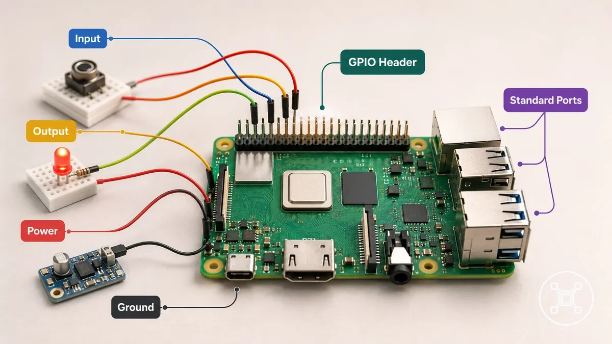
The Raspberry Pi GPIO header separates connection roles on the board. Programmable pins are used for input and output signal control, while power pins provide electrical supply connections and ground pins provide circuit reference connections. Identifying the correct header connection is required before attaching a component because GPIO pins, power pins, and ground pins serve different purposes.
The Raspberry Pi GPIO header separates connection roles on the board.
A common misunderstanding is that every GPIO header pin works as a programmable signal connection. GPIO pins have specific roles, and not every pin is suitable for every electronic component or connection type. The Raspberry Pi ports and connectivity section covers standard board connections such as USB, HDMI, Ethernet, and wireless communication, while GPIO focuses on programmable input, output, and signal connections.
How the 40-pin GPIO header is arranged
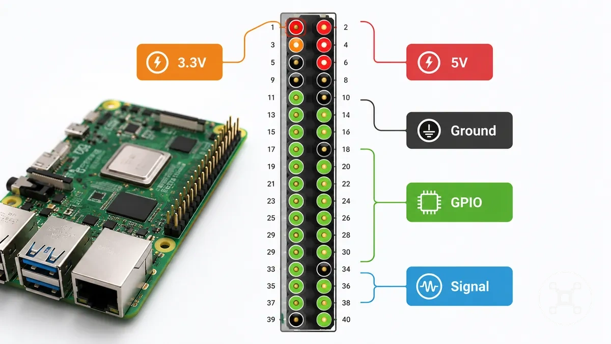
The 40-pin GPIO header is arranged as two rows of physical pins on a Raspberry Pi board, with each pin position linked to a specific electrical role. The pinout identifies the physical pin location, orientation, and function of each connection. Understanding the 40-pin header helps beginners distinguish pin placement from electrical purpose before connecting hardware.
The pinout identifies the physical pin location, orientation, and function of each connection.
When a component is connected to the header, the physical pin location must be matched with the required electrical role. The header layout combines position with functions such as power, ground, GPIO signal connections, and interface pins. Checking the Raspberry Pi specifications helps confirm board-specific hardware details before using the pinout reference.
How the 40-pin GPIO header is arranged depends on both physical location and pin role.
How the 40-pin GPIO header is arranged depends on both physical location and pin role. The two header rows provide a layout reference, while power pins, ground pins, programmable GPIO pins, and interface pins represent different connection purposes. A physical pin number identifies where a connection is located, but the electrical role must also be verified using the correct board model pinout.
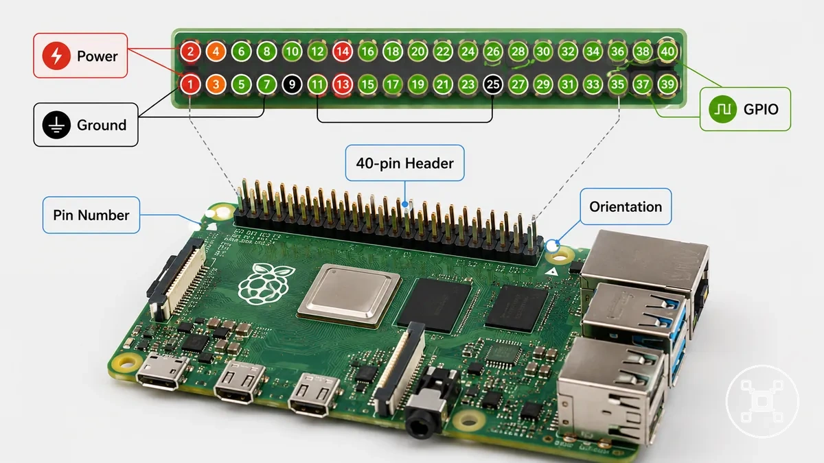
The following table separates the header by electrical role so beginners can check both the physical position and the connection purpose.
| Pin group | What it represents | Beginner check |
|---|---|---|
| Power pins | Electrical supply connections on the header | Confirm the required power connection before attaching a component |
| Ground pins | Circuit reference connections | Match the ground connection with the intended circuit path |
| Programmable GPIO pins | GPIO connections used for input and output signals | Check the pinout before assigning a signal role |
| Interface pins | GPIO header connections used for specific communication functions | Verify the interface requirement and board model |
Physical pin numbers and GPIO names
Physical pin numbers and GPIO names identify a header position using two different numbering systems. A physical pin number shows the location of a pin on the GPIO header, while a GPIO name identifies the related signal label used for control. The distinction helps prevent confusion when reading a pinout or following a code example.
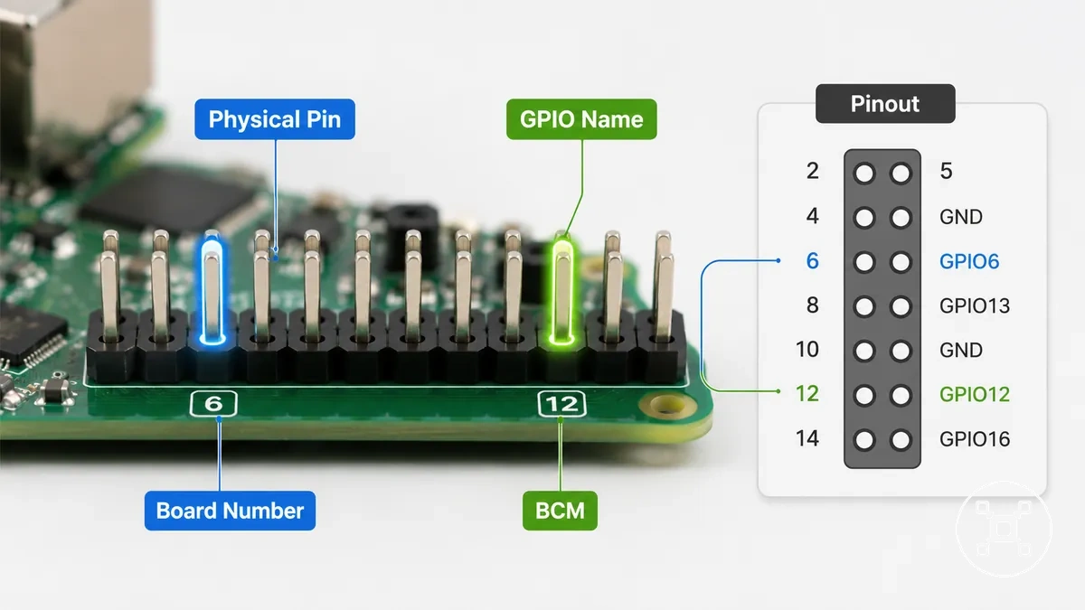
A common wiring mistake happens when board numbering and BCM numbering are mixed. Physical pin numbers refer to the header position, while BCM numbering refers to GPIO names used by software references. A code example must use the expected numbering mode because mixing the two systems can cause a connection or control error at the wrong header position.
| Naming system | What it identifies |
|---|---|
| Physical pin number | The header position of a specific pin on the board |
| GPIO name | The GPIO label associated with the signal connection |
| Board numbering | The numbering mode based on physical header positions |
| BCM numbering | The numbering mode based on GPIO signal names |
Power, ground, and programmable pins
Power, ground, and programmable pins serve different electrical jobs on the Raspberry Pi GPIO header. Power pins provide supply connections, ground pins provide circuit reference paths, and programmable GPIO pins provide controllable signal connections for input and output functions. These roles separate fixed electrical pins from pins that software can configure.
These roles separate fixed electrical pins from pins that software can configure.
The GPIO header contains different pin types, so each connection should be identified before attaching a component. The main roles are separated below:
- Power pin: Provides a fixed supply connection with voltage values such as 3.3V or 5V. The required voltage and current limits should be checked before connecting a component for safe use.
- Ground pin: Provides a circuit reference and return path for the electrical connection. The ground connection should match the intended circuit design before wiring.
- Programmable GPIO: Provides controllable signal connections that can be configured for input or output behavior. The signal role depends on the software configuration and connected component requirements.
- Interface pin: Provides a GPIO connection used for specific communication functions. The interface requirement should be verified with the component and board configuration before use.
GPIO pin functions and interface roles
GPIO functions and interface roles describe the different ways Raspberry Pi GPIO connections can be used after the physical header layout is understood. GPIO pins can support digital input, digital output, and other configured functions based on the selected pin assignment. This section focuses on how GPIO pin functions and interface roles affect signal connections.
This section focuses on how GPIO pin functions and interface roles affect signal connections.
Different components require different GPIO functions because their signal needs and connection methods are not the same. A sensor may use digital input, an LED may use digital output, and communication devices may require specific interface roles. The selected function should match the component, wiring method, and board configuration to maintain safe use.
One physical pin can support different roles depending on configuration and pin assignment.
One physical pin can support different roles depending on configuration and pin assignment. The table below separates common GPIO functions and interface roles by their condition, behavior, and practical effect.
| Entity/part | Attribute/criterion | Value/condition | Effect/risk/decision |
|---|---|---|---|
| GPIO pin | Signal direction | Digital input or digital output | Input reads signals, while output sends control signals to connected components |
| GPIO configuration | Signal state control | Pull-up or pull-down behavior | Provides a defined signal state based on the configured condition |
| GPIO function | Output control | PWM signal generation | Used when a component requires a controlled output signal pattern |
| Interface role | Communication type | I2C, SPI, or UART | The interface should match the component requirement and pin assignment |
Input pins, output pins, and signal behavior
Signal direction changes the job of a Raspberry Pi GPIO connection. An input pin reads a signal condition from a connected component, while an output pin sends a signal condition to a connected component. This local distinction defines how input pins, output pins, and signal behavior are used.
Signal direction changes the job of a Raspberry Pi GPIO connection.
An input pin and an output pin should match the role of the connected component and its configuration. A button can provide an input state that the Raspberry Pi reads, while an LED can receive an output state controlled through a GPIO connection. High level and low level states describe different digital signal conditions, while a pull resistor such as pull-up or pull-down can help define an input state when the signal condition requires it. Incorrect direction settings can create a wiring mistake, so the signal direction and connected component requirements should be checked before use.
I2C, SPI, UART, and PWM pins
I2C, SPI, UART, and PWM pins describe special interface roles that some Raspberry Pi GPIO connections can support for specific communication and control tasks. Interface pins group signals for methods such as device communication and output control. This section focuses on the local role of I2C, SPI, UART, and PWM pins within GPIO configurations.
Interface pins group signals for methods such as device communication and output control.
Different components use different interface roles because their communication requirements are not the same. A sensor may use I2C, a display or module may use SPI or UART, and PWM may be used when a component requires a controlled signal pattern. The required pin assignment and configuration should match the component and board setup to reduce wiring risks.
| Interface | Typical connected part | Required pin behavior | Setup implication |
|---|---|---|---|
| I2C | Sensor or compatible module | GPIO connections assigned for I2C communication | Confirm the pin assignment and configuration required by the component |
| SPI | Display or module | GPIO connections assigned for SPI communication | Match the interface role with the connected component requirements |
| UART | Communication module | GPIO connections assigned for serial communication | Verify the communication configuration before wiring |
| PWM | Component requiring controlled signal output | Configurable signal output behavior | Check the pin assignment and component needs before use |
What GPIO pins can control or read
A Raspberry Pi GPIO pin can control or read signals from connected electronic components such as LEDs, buttons, sensors, relays through driver circuitry, and small modules. GPIO connections can read a signal condition or send a control signal depending on the component and configuration. This section focuses on the realistic control and reading roles of Raspberry Pi GPIO pins.
This section focuses on the realistic control and reading roles of Raspberry Pi GPIO pins.
Different components require different GPIO roles because their signal requirements and current needs vary. An LED can use a GPIO output signal to show a status state, while a button or sensor can provide an input signal that the Raspberry Pi reads. A relay requires a driver circuit because the GPIO pin is limited to signal control rather than directly handling higher-power switching. Small modules may require specific wiring and configuration conditions before they can be controlled or read safely.
- LED: Uses a GPIO output signal to control a status indication. The connection should account for the component requirements and current limit of the GPIO connection.
- Button: Uses a GPIO input signal to read a switch state. The input configuration and wiring condition should match the button circuit to provide a reliable signal.
- Sensor: Uses a GPIO input or communication signal to provide information to the Raspberry Pi. The sensor type and configuration determine how the signal is read.
- Relay: Uses a GPIO control signal through a driver circuit. The driver circuit separates the GPIO connection from the higher-current load requirements of the relay.
- Module: Uses GPIO connections for control, communication, or status signals. The required pin assignment and configuration should match the module requirements before use.
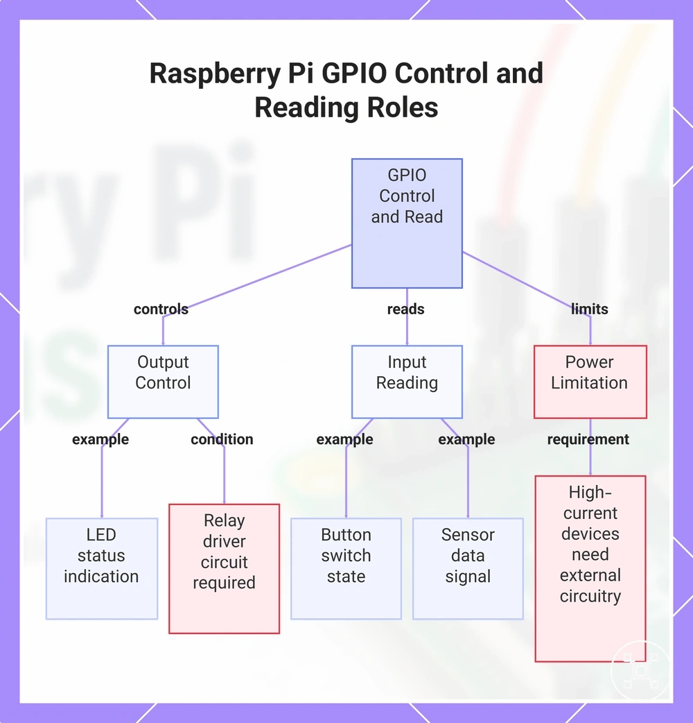
GPIO pins separate three different tasks: reading a signal, controlling a signal, and powering a device. GPIO connections can control or read components when the signal type, wiring, and configuration match the intended use. Devices with higher current requirements need additional circuitry rather than direct GPIO connection.
Devices with higher current requirements need additional circuitry rather than direct GPIO connection.
This chart shows the main roles of Raspberry Pi GPIO pins: controlling output signals, reading input signals, and the limitation of powering high-current devices.
Connecting GPIO pins with jumper wires and breadboards
Connecting GPIO pins with jumper wires and breadboards creates temporary GPIO connections for learning and prototyping with a Raspberry Pi. The wiring path must follow the GPIO header pin role, breadboard row continuity, and component requirements. This section focuses on how jumper wires and breadboards create temporary connection paths between GPIO connections and electronic components.
The wiring path must follow the GPIO header pin role, breadboard row continuity, and component requirements.
A typical prototype uses jumper wires to connect Raspberry Pi header pins to breadboard rows, power rails, and component legs. The breadboard creates temporary electrical paths, while a resistor can be placed between connections when the circuit requires additional control of the signal path. A clear example keeps the power rail, ground rail, and signal path separate so each connection purpose remains identifiable. The wiring arrangement should match the component requirements and GPIO configuration before applying power.
- GPIO header: Provides the starting connection points for GPIO connections. The selected header pin should match the required power, ground, or signal path.
- Jumper wires: Create temporary links between the GPIO header, breadboard rows, and component legs. Each wire end should connect to the intended row or pin location.
- Breadboard rows: Provide temporary connection paths through connected rows. Row continuity should be checked when placing components.
- Power rail and ground rail: Provide separate paths for supply and reference connections. Keeping these rails distinct helps maintain clear power and ground wiring.
- Resistor and component leg: Form part of the circuit path when a component requires a resistor connection. The resistor placement and component leg position should match the intended circuit design.
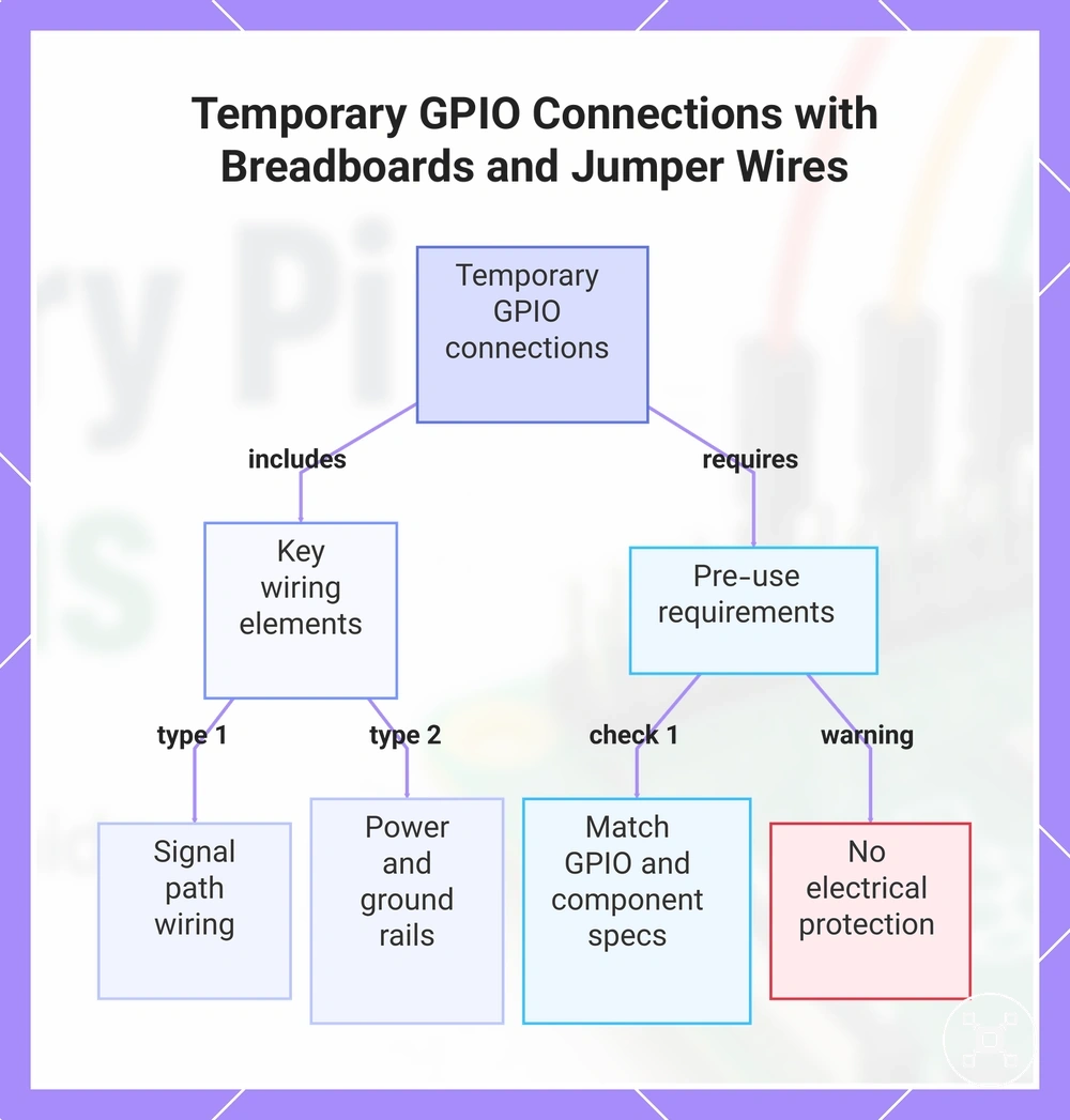
A simple connection pattern keeps the GPIO signal path separate from the power rail and ground rail: one jumper wire carries the signal connection, while separate connections provide power and ground where required. A breadboard supports temporary prototyping but does not provide electrical protection, so the component, wiring, and configuration conditions should be checked before use.
This chart shows the main wiring elements and pre-use checks for creating temporary GPIO connections with jumper wires and breadboards on a Raspberry Pi.
This chart shows the main wiring elements and pre-use checks for creating temporary GPIO connections with jumper wires and breadboards on a Raspberry Pi.
Breadboard rails, rows, and GPIO connections
Breadboard continuity determines whether parts connected to a Raspberry Pi GPIO circuit are actually connected. Breadboard rows, power rails, and ground rails create different connection paths, so component placement affects how GPIO connections behave. This section focuses on the local wiring relationship between breadboard rails, rows, and GPIO connections.
The row continuity and connection arrangement should be checked before applying power to a GPIO circuit.
A breadboard layout uses terminal rows, a center gap, and rails to organize component placement and signal routing. Components placed in connected breadboard rows share a path, while the center gap separates the two sides of the board layout. Power rails and ground rails provide dedicated paths for supply and reference connections, and the signal routing path depends on where each component leg and wiring point is placed. The row continuity and connection arrangement should be checked before applying power to a GPIO circuit.
- Breadboard rows: Provide terminal connection points for component placement. The continuity of each row determines whether component legs share the same electrical path.
- Center gap: Separates the two sides of the breadboard. Component placement across or beside the gap changes how parts connect within the circuit.
- Power rails: Provide a dedicated path for supply connections. The selected rail should match the intended power connection in the circuit.
- Ground rails: Provide a dedicated path for ground connections. Keeping ground connections separate from signal routing helps maintain a clear circuit path.
- Signal routing: Defines the path between GPIO connections and component legs. The wiring path should be traced through rows and rails before testing the circuit.
Jumper wire types for GPIO headers
Jumper wire types for GPIO headers determine how Raspberry Pi GPIO connections attach to header pins and breadboards. Male-to-female, male-to-male, and female-to-female jumper wires have different connector ends for different connection points. This section focuses on the connector fit of jumper wire types for GPIO headers.
This section focuses on the connector fit of jumper wire types for GPIO headers.
The correct jumper wire depends on whether the connection point is a GPIO header, breadboard, or another wiring point. Connector fit affects how securely a connection is made, while an unsuitable wire end type can create a loose connection or wiring mistake. The wire type should match the physical layout and circuit configuration before use.
- Male-to-female jumper wire: Uses a male connector end for a breadboard connection and a female connector end for a GPIO header pin. The connector fit matches setups where the Raspberry Pi header and breadboard require different connection ends.
- Male-to-male jumper wire: Uses male connector ends on both sides for breadboard connections and other pin-style connection points. The connection point should accept the connector end to maintain the intended wiring path.
- Female-to-female jumper wire: Uses female connector ends on both sides for connections between compatible pin-style points. The connector fit should match the receiving pins to avoid an unstable connection.
Using sensors and simple components with GPIO
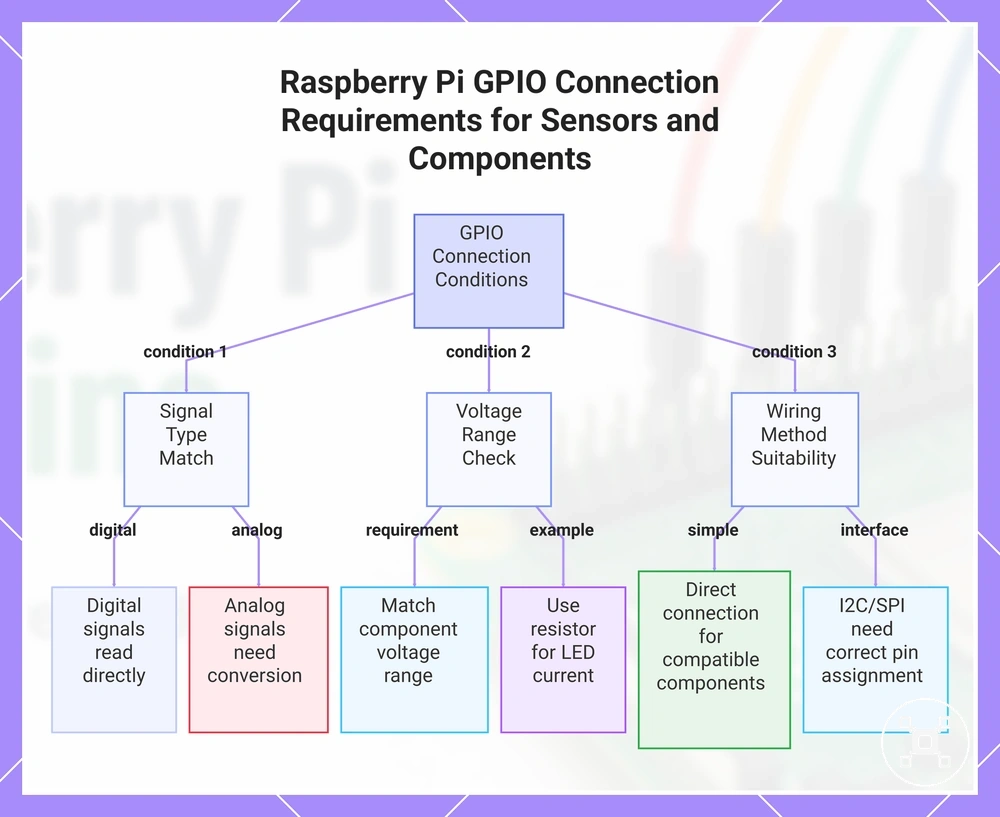
A Raspberry Pi GPIO connection can work with a sensor or simple component when the signal type, voltage range, and wiring method match the component requirements. A digital signal can be read or controlled through GPIO, while an analog output requires a suitable conversion method before the Raspberry Pi can process the value. This section focuses on the local use of sensors and simple components with GPIO connections.
This section focuses on the local use of sensors and simple components with GPIO connections.
Different components require different GPIO conditions because their signals and electrical requirements are not the same. A button can provide a digital signal, while an LED can use a GPIO output signal with a resistor to help manage the connection conditions. An I2C module or SPI module uses its communication interface when the GPIO configuration and pin assignment support the required connection method. The component type and voltage range should be checked before connecting the circuit to maintain a suitable wiring condition.
- Digital sensor: Uses a digital signal that GPIO can read when the sensor output and Raspberry Pi GPIO configuration match. The sensor voltage range and wiring method should match the GPIO requirements before use.
- Analog-output sensor: Provides an analog output that GPIO may not read directly without a conversion method. A suitable converter is required when the Raspberry Pi needs to interpret an analog value.
- Button: Uses a digital signal input to indicate a switch state. The button wiring and GPIO configuration should match the intended input condition.
- LED: Uses a GPIO output signal to control an indicator state. A resistor can be used in the circuit to manage the current conditions for the LED connection.
- I2C module or SPI module: Uses a communication interface through GPIO connections. The interface type, pin assignment, and configuration should match the module requirements before connection.
- Simple component: Uses a GPIO signal when its electrical requirements match the available GPIO capability. Components requiring different current conditions need additional circuitry rather than direct GPIO connection.
Choosing a GPIO project starts with matching the component signal type, voltage range, and wiring method to the Raspberry Pi GPIO capability. A sensor or simple component should be connected according to its signal requirements and configuration conditions. This helps keep the signal path appropriate and reduces the risk of unsuitable connections.
This helps keep the signal path appropriate and reduces the risk of unsuitable connections.
This chart shows the three main conditions to check when connecting a sensor or simple component to a Raspberry Pi GPIO: signal type, voltage range, and wiring method.
GPIO compatibility across Raspberry Pi boards
GPIO compatibility across Raspberry Pi boards depends on header presence, pinout continuity, board generation, and accessory fit. A GPIO connection that works with one board model should be checked against the physical layout and configuration of another board before connecting hardware. This section focuses on the compatibility conditions that affect GPIO use across Raspberry Pi boards.
This section focuses on the compatibility conditions that affect GPIO use across Raspberry Pi boards.
The Raspberry Pi specifications provide board criteria that help identify hardware differences affecting GPIO connections. A 40-pin header provides a common GPIO connection layout on many boards, while smaller boards or older layouts may require verification of their available header pins and pinout continuity. HAT and extension compatibility depends on the board model, software configuration, and physical clearance around the GPIO area. The board model should be confirmed when accessory fit, connector alignment, or software pin numbering affects the connection decision.
| Item | Compatibility condition | Practical decision |
|---|---|---|
| 40-pin header | Requires matching header presence and pinout continuity | Verify the board model before connecting GPIO accessories |
| Smaller boards | May have different header arrangements or available GPIO connections | Check the physical pin layout before using hardware designed for another board |
| Older layouts | Require confirmation of header configuration and pin assignment | Compare the board model with the accessory requirements |
| HAT or extension | Requires matching GPIO connections, software configuration, and physical clearance | Confirm fit and configuration before installation |
| Software pin numbering | Requires the correct numbering method for the selected board configuration | Match software references with the intended GPIO assignment |
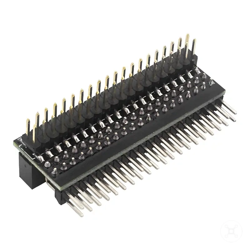
GPIO extensions, breakout boards, and header accessories
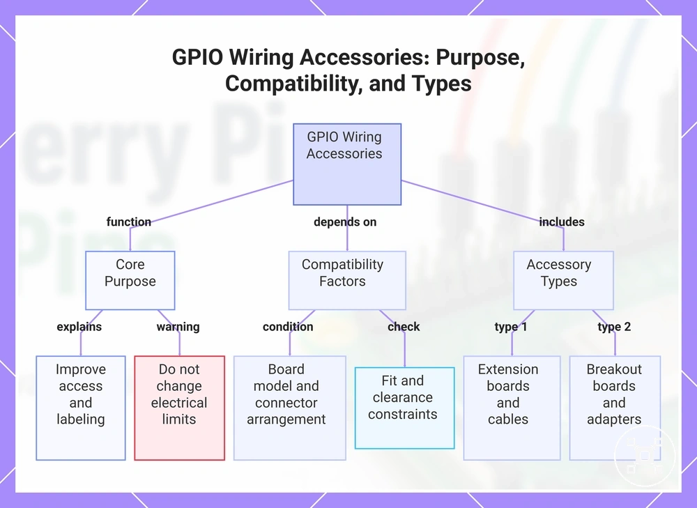
GPIO extensions, breakout boards, and header accessories can make Raspberry Pi GPIO wiring easier by improving access, labeling, spacing, or connection layout without changing the electrical limits of GPIO connections. The compatibility of each accessory depends on the board model, connector arrangement, fit constraint, and intended wiring method. This section focuses on the local compatibility factors for GPIO extensions, breakout boards, and header accessories.
Accessory choice should match the Raspberry Pi GPIO layout and the physical requirements of the setup.
Accessory choice should match the Raspberry Pi GPIO layout and the physical requirements of the setup. A GPIO extension board can improve access to header pins, while a breakout board can provide clearer labeling for GPIO connections during prototyping. Ribbon cable, pin header arrangements, and breadboard adapters require matching connector fit and physical clearance before use. Accessories can organize wiring, but they do not make unsuitable signal paths or incorrect connections safe by default.
- GPIO extension board: Improves access to GPIO connections by changing the physical reach or layout of header pins. Compatibility depends on the board model, connector arrangement, and available space.
- Breakout board: Provides a more accessible wiring layout with labeling for GPIO connections. The pin arrangement should match the required GPIO header layout before connection.
- Ribbon cable: Extends GPIO header access to another location. The cable orientation, connector fit, and board layout should match the intended connection path.
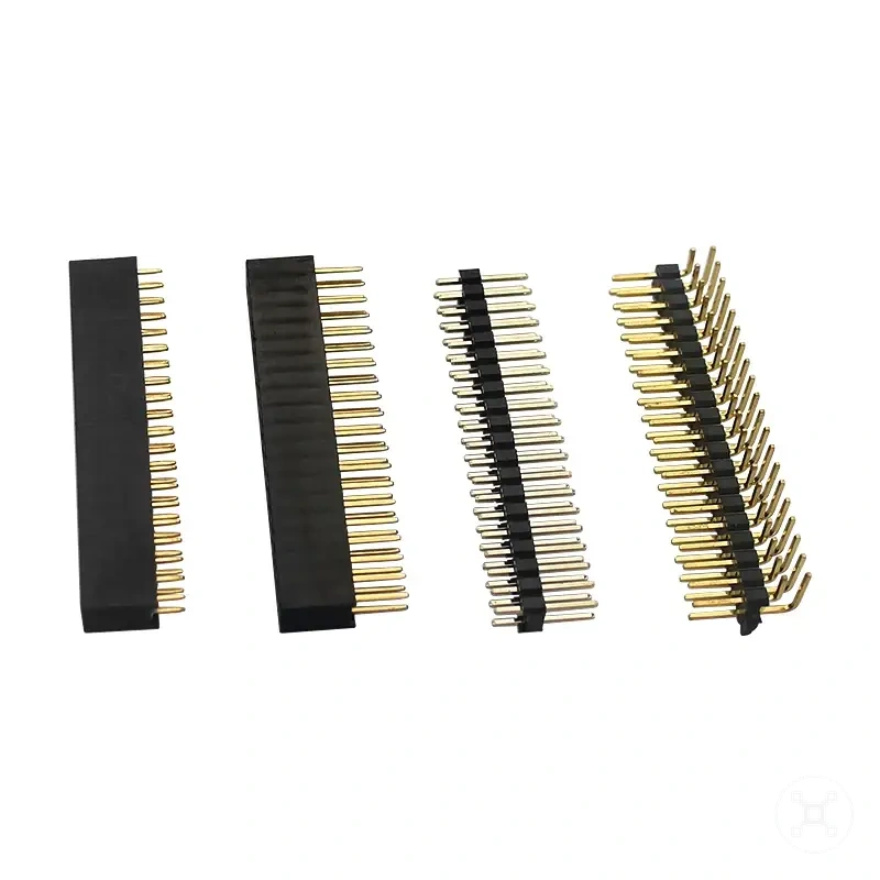
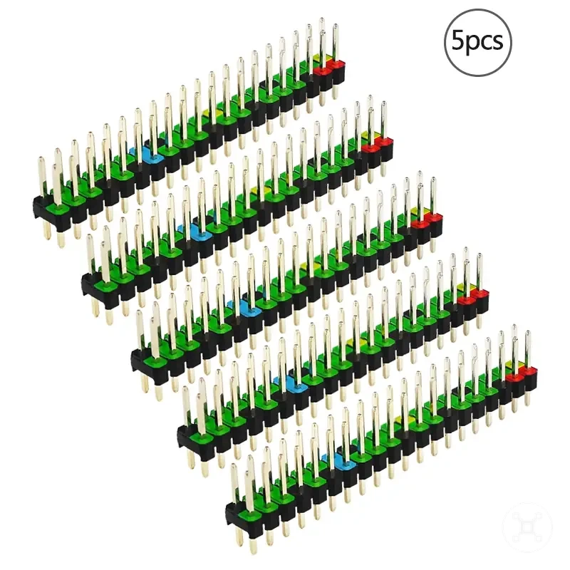
- Pin header: Provides physical connection points for GPIO accessories. The header arrangement must match the required wiring points and accessory design.
- Breadboard adapter: Connects GPIO header pins to a breadboard-based prototype setup. The adapter fit and wiring layout should match the board configuration.
- Labeling: Helps identify GPIO connections during wiring. Labels should be checked against the actual pin assignment before connecting components.
GPIO accessories are useful when easier access, clearer identification, or repeated prototyping is the main goal. Beginners may find breakout boards and labeling useful for reducing wiring confusion, while cramped cases may require accessories that address physical clearance constraints. The board model, accessory fit, and connection requirements should be verified before use.
The board model, accessory fit, and connection requirements should be verified before use.
This chart shows the main purpose, compatibility factors, and common types of GPIO wiring accessories for Raspberry Pi.
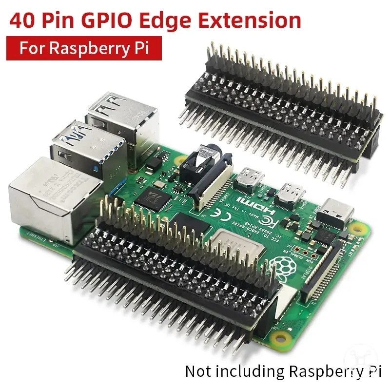
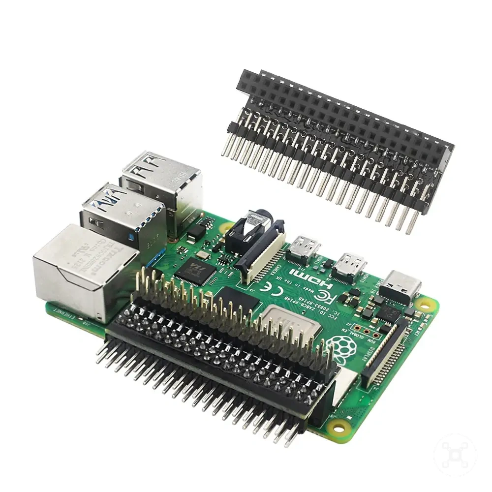
Here are product examples that may make comparison easier. Before buying, always review the compatibility criteria, essential features, and product details.
GPIO safety limits and protection basics
GPIO safety depends on matching Raspberry Pi GPIO connections with suitable voltage, current, wiring direction, and component protection conditions. A circuit that appears simple can still require protection components when the connected device introduces different electrical requirements. This section focuses on the local GPIO safety limits and protection basics.
This section focuses on the local GPIO safety limits and protection basics.
GPIO connections should be checked for signal conditions, component requirements, and protection methods before use. The following checklist identifies common risk conditions, the possible effect, and the protection action that helps reduce unsuitable connections.
- 3.3V logic: Raspberry Pi GPIO signals use 3.3V logic conditions. Components with different signal levels require a suitable interface method before connecting to GPIO connections.
- 5V exposure: A GPIO pin exposed to a higher voltage condition can create a risk for the board. A level shifter or another suitable interface method may be required when voltage levels do not match.
- Current limit: GPIO pins provide signal control rather than direct power for higher-current components. A driver circuit should be used when a component requires electrical conditions beyond the GPIO connection capability.
- Resistor: Components such as LEDs may require a resistor to manage the current path in the circuit. A resistor helps match the component requirements with the intended GPIO connection.
- Short circuit: Incorrect wiring between power and ground paths can create a short circuit condition. Checking wiring direction and connection paths before power is applied helps reduce this risk.
- Common ground: Components using GPIO signals may require a shared common ground reference. The ground connection should match the circuit design for the signal path to operate correctly.
- Level shifter or isolation: Components with different voltage conditions or electrical requirements may need a level shifter, isolation method, or driver circuit before connection.
A simple-looking circuit may still need a resistor, level shifter, or driver circuit when the component signal type, voltage range, or current requirement does not match Raspberry Pi GPIO conditions. Checking the component requirements and protection method before connection helps maintain a safer GPIO setup.
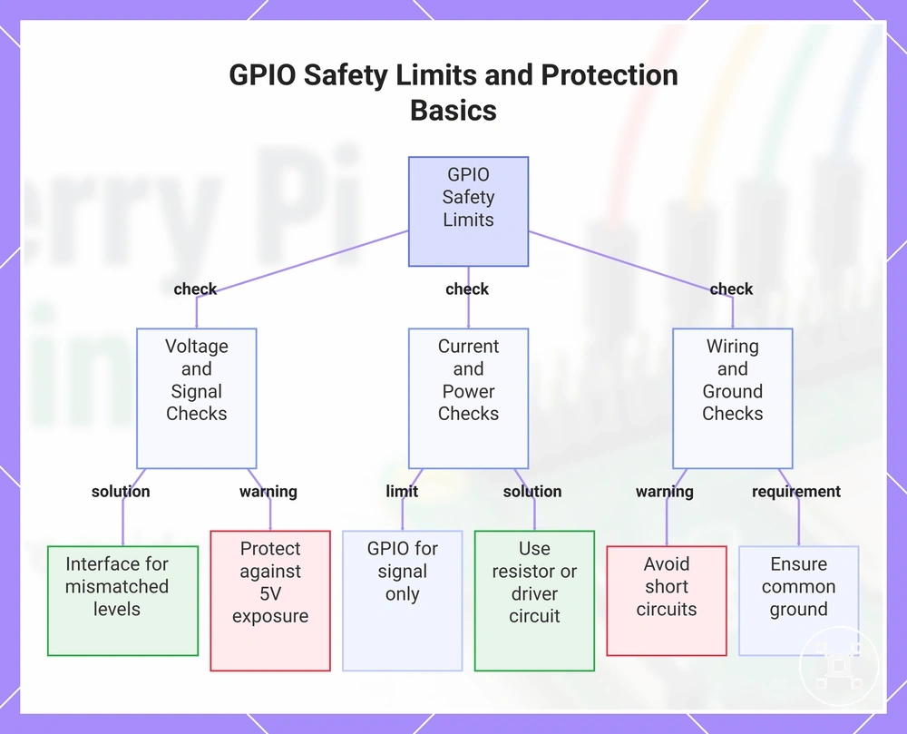
This chart shows the main safety checks and protection methods for Raspberry Pi GPIO connections.
This chart shows the main safety checks and protection methods for Raspberry Pi GPIO connections.
Voltage limits and 5V risks
Raspberry Pi GPIO pins should be treated as 3.3V logic connections because a voltage mismatch can create a risk even when a circuit appears small or simple. A 5V risk can occur when a device sends an unsuitable signal level to a GPIO input pin or when wiring confuses a signal connection with a power pin. This section focuses on the local voltage limits and 5V risks of GPIO connections.
This section focuses on the local voltage limits and 5V risks of GPIO connections.
The following warning checklist identifies voltage-related conditions that require attention before connecting components.
- 3.3V logic: Raspberry Pi GPIO connections use 3.3V logic conditions. A component that outputs a different signal level should use a suitable interface method before reaching an input pin.
- 5V logic device: A 5V logic device connected directly to a GPIO input can create a voltage mismatch. A level shifter may be required when the signal level from the device does not match the GPIO input requirements.
- Sensor output: A sensor output should be checked before connecting it to a GPIO input pin. The output signal condition determines whether additional conversion or protection is needed.
- Power pin confusion: Connecting a signal wire to a power pin instead of the intended GPIO connection can create an unsuitable electrical condition. Header pin identification should be checked before wiring.
A simple-looking circuit may still need a level shifter or another protection method when the component output, voltage condition, or wiring arrangement does not match Raspberry Pi GPIO requirements. Checking the sensor output, input pin role, and connection path before use helps reduce the risk of unsuitable voltage conditions.
Short circuits, current load, and protection parts
Safe Raspberry Pi GPIO wiring depends on limiting current load and preventing unintended connections through the circuit path. A short circuit or unsuitable current condition can create a risk when electrical flow reaches the wrong path or exceeds what a GPIO connection should handle. This section focuses on the local protection role of short circuits, current load, and protection parts.
This section focuses on the local protection role of short circuits, current load, and protection parts.
The following checklist identifies component conditions that can create risks and the protection actions that help maintain suitable GPIO connections.
- Resistor: A resistor controls the current path for components that require current management. A missing or unsuitable resistor can create an unsuitable condition for the connected component and GPIO circuit.
- Current load: A component with a higher current requirement should not be driven directly through a GPIO connection when the load exceeds the pin capability. A transistor driver or relay driver separates the GPIO signal path from the higher-current component path.
- Short circuit: A direct connection between unintended circuit paths can create a short circuit condition. Checking wiring points and power connections before applying power helps reduce this risk.
- Shared ground: A shared ground provides a common reference path between connected components. The ground connection should match the circuit design so signal conditions remain suitable.
- Transistor driver and relay driver: Driver circuits allow GPIO connections to control components with different current requirements. The driver provides a separate control path between the GPIO signal and the connected load.
- Polarity: Component polarity determines the required connection direction for parts with directional electrical behavior. Checking polarity before wiring helps prevent unsuitable circuit conditions.
Software settings alone cannot prevent electrical damage caused by incorrect wiring, excessive current, or unsuitable component connections. Protection parts and circuit checks should match the component requirements, wiring arrangement, and GPIO configuration before applying power.
Common GPIO mistakes and connection problems
Common GPIO mistakes and connection problems are usually caused by wrong pin numbering, wiring continuity issues, voltage mismatch, missing ground connections, or incorrect component assumptions. Checking the Raspberry Pi GPIO configuration, wiring path, and connected components first can help identify the likely problem before broader hardware diagnosis. This section focuses on the local diagnosis of Common GPIO mistakes and connection problems.
This section focuses on the local diagnosis of Common GPIO mistakes and connection problems.
The following troubleshooting table matches common GPIO symptoms with likely causes, checks, and the meaning of each result.
| Symptom | Likely attribute issue | Check | What it means |
|---|---|---|---|
| GPIO signal does not respond | Wrong pin numbering | Confirm the numbering mode in the code and compare it with the physical GPIO header pins | The software reference and physical GPIO connection may not point to the same pin |
| Component does not activate | Reversed wire | Trace the wiring path between GPIO connections and the component | The signal path may not reach the intended connection point |
| LED or component behaves unexpectedly | Missing resistor or incorrect component assumption | Check the component requirements and circuit arrangement | The circuit may require additional protection or a different wiring method |
| Input signal is not detected | Missing ground or incorrect interface | Check the shared ground connection and confirm the selected interface pins | The GPIO input may not have the required reference or communication path |
| GPIO device behaves incorrectly | Voltage mismatch | Check whether the device output signal matches the GPIO input requirements | A suitable conversion method may be required before connection |
| Prototype works intermittently | Loose breadboard connection | Check breadboard placement, wiring points, and physical connections | The signal condition may change because the connection is unstable |
GPIO-specific diagnosis should focus on wiring, pin assignment, component connection, and configuration before moving to broader hardware issues. Problems involving Raspberry Pi ports and connectivity belong to a wider connection scope when the issue is outside GPIO-specific diagnosis.
The troubleshooting approach can also differ when comparing Raspberry Pi GPIO behavior with other platforms.
The troubleshooting approach can also differ when comparing Raspberry Pi GPIO behavior with other platforms. The differences explained in Raspberry Pi vs microcontroller boards can help identify whether the issue relates to platform design rather than a GPIO connection problem.